Download

1 / 36
360 likes | 565 Vues
A Distributed Communication System in a Humanoid Robot. Milton Ruas 1 Filipe M. T. Silva 1 Vítor M. F. Santos 2. 1 Department of Electronics and Telecommunications 2 Department of Mechanical Engineering University of Aveiro , PORTUGAL. Overview. Introduction Distributed Control System

E N D
A Distributed Communication System in a Humanoid Robot Milton Ruas1 Filipe M. T. Silva1 Vítor M. F. Santos2 1 Department of Electronics and Telecommunications 2 Department of Mechanical Engineering University of Aveiro, PORTUGAL
Overview • Introduction • Distributed Control System • The Communications System Model • PC-Master Communication • RS-232 communication • RS-232 messages and protocol • Master-Slaves communication • CAN: an introduction • CAN configuration in a PIC18F258 • CAN messages and protocol • System variables access • Conclusions and Future perspectives
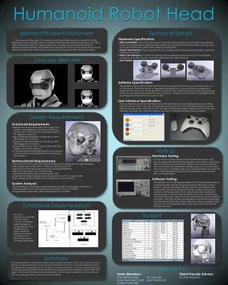
Introduction • Complete humanoid model • 22 degrees of freedom • Weight - 5 kg • Height - 60 cm • Max. width - 25 cm • Foot print - 20 8 (cm2) • Actuation • Servomotors with transmission belts • Sensors • A vision Camera • Servos’ position (through its internal potentiometers) • Sensitive foot to applied forces • Accelerometers/Inclinometers • Gyroscopes
Local Control • Each slave controller is made of a PIC 18F258 device with I/O interfacing • All slave units: • Connect up to 3 servomotors • Have a common base (a piggy-back unit can add I/O sensors)
Main Control RS232 Master CAN BUS Slaves 3 3 1 2 2 2 2 1 1 1 3 3 2 2 1 1 3 3 2 2 1 1 Distributed Control System • A Main Control Unit (PC): • Exchanges high-level orders and interacts with the camera. • RS-232 communication with the Distributer unit. • Distributer Unit (Master): • Interface between the Main and the Local control units. • Adapts the RS-232 to CAN commands (and vice-versa). • 8 Local Control Units (Slaves): • Control the low-level features of the several devices. • CAN bus to connect them.
PC-Master Communication • Communication system: RS-232 • Data to be exchanged: • Actuation • Final position (3 components) • Mean velocity for the 3 components • Type of Controller • Controller gains (2+1) • Sensors information • Servomotors position (3) • Servomotors mean velocity (3) • Servomotors current consumption (3) • Special sensors data (4) PC Master
RS-232 Communication • Exchange Model • Request/Response from Main Unit to Master • RS-232 Setup: • Asynchronous flow • 1 start + 8 data + 1 parity + 1 stop bits • Baudrate: 115K2 bps • Messages: • Start of Frame (SOF) • OpCode: Operation Code • ... • BCC: EXOR of Full message PC Master 1 byte 1 byte 3/4 bytes 1 byte MessageStructure (bytes) RS-232 character (bits)
RS-232 Messages Actuation Servos: SensorsReading Potentiom: Special: InvalidRequest
RS-232 Messages OpCode:
RS-232 Algorithms Start Start Prepare message Timeout Error Yes #ReTX >10 ? Characterreceived? No No Yes Retransmition? Reset Yes No Frame/Overrunerror? Yes Clearerror TransmitMessage No Characterstoredin RX buffer SOF Reception Remainder response RX Full RX buffer? No Yes Validate Response Processmessage & prepare response Return Response ReturnErrormessage Transmit Response PC Master
RS-232 Commands (examples) • Communications initialization • H=initcom(1,115200) % COM1, Baud=115k2 • Joints Actuation • Applyjoint(H,2,0,[0 0 70]) % SCU=2, pos=[0 0 70] • Motion velocity • Applyjoint(H,2,1,[100 100 100]) % Period=[2 2 2]s • Joints position reading • Readjoint(H,2,0) [pos1 pos2 pos3] • Force sensors reading • ReadSpecial(H,2) [data1 data2 data3 data4]
Master-Slaves Communication • Communication system: CAN • Data to be exchanged: • Actuation • Final position to reach (3 components) • Mean velocity (3 components) • Type of Controller • Controller gains (2+1) • Sensors information • Servomotors position (3) • Servomotors mean velocity (3) • Status of the slave unit • Servomotors current consumption (3) • Special sensors data (4) CAN x8
Communication • Developed by Robert Bosch in the 1980s • Initially applied in the automotive industry, but soon has expanded to other fields: • Very reliable and Robust • Easy to add/remove nodes • Ideal for Real Time Distributed Control • CAN: • MAC based on CSMA/CR to control collisions • Message prioritisation • Broadcast messages • Guaranteed data consistency • Acknowledgment • Fault tolerance • Error detection and signalization • Automatic error recovery
Stack • CAN is based on the traditional OSI model • Only the Physical and Datalink layers are used: • Physical layer • Bit encoding/decoding • Bit timing • Bit synchronization • Datalink layers • Logical Link Control (LLC) • Reception • Masking/Filtering • Recovery management • Medium Access Control (MAC) • Data encapsuling • Frame encoding • Medium Access management • Error detection and Signalization
Physical Layer • Bit Encoding • NRZ: Non return to zero • Each bit is composed by several time quantums • Synchronization: • Bit stuffing 5 bits • Synchronization between nodes: • Interrupt generation inside the bit time after successful RX/TX • Maximum #nodes: • 32, 64, 128... Depends on the line transceivers • Transmission rate: • From 5kb/s (10km) to 1Mb/s (40m) • Depends on the time quantums used.
Data Link Layer • MAC: CSMA/CR • Non-destructive arbitration at bit level • In a collision in the access bus, the highest priority message is selected without any delay. • Errors signalled in the CAN data frame.
Versions • CAN 2.0A (Basic CAN) • Partial filtering • RTRs processing and messages acceptance made at the application layer • Only one Buffer for RX, and one for TX • High overhead at the application level • CAN 2.0B (Full CAN) • Total filtering. • 16 buffers can be programmed for RX/TX • Low overhead at the application level • PIC 18F2x8x implements the full CAN version
Protocol CAN ID • CAN ID information: • Source address: transmitter node address • Destination address: receiver node address • Index: Index of message (1st or 2nd) • Type of operation: Actuation/Sensor reading • 2 types of messages exchanged (operation): • Actuation: from Master to Slaves • Sensor reading: from Slaves to Master • Each message is composed of 2 CAN packets to accommodate all the necessary information. • Prioritized messages: • Actuation messages (from Master to Slaves) have higher priority • Lower address nodes have higher priority • First packet of each message have higher priority
Protocol CAN ID • Lower Parts (legs and hips) have higher priority than others • Priority defined according to the part importance
Protocol Actuation: Master Slaves Msg1 Msg2 Sensor reading: Slave Master Msg1 Msg2
in PIC 18F258 • PIC 18F258 basic specifications: • Message bitrates up to 1Mbps • 11/29-bit ID fields (Normal/Extended CAN) • Up to 8 bytes of message length • 3 prioritized TX buffers + 2 RX buffers • 6 full prioritized, 29-bit acceptance filters • Overflow RX prevention • Advanced error management features • Configuration of CAN: • Enter in Configuration Mode: avoids accidental reconfiguration • Configure Baudrate • Configure Mask & Filters for message acceptance • How messages should be transmitted/received • Enter in Normal Mode: ready to exchange messages
Initial Configuration: Baudrate • Registers to setup: • BRP=2 Quanta duration (depends of the crystal frequency) • PRSEG Propagation Segment (1..8 2) • SEG1PH Phase Segment 1 (1..8 3) • SEG2PH Phase Segment 2 (2..8 2) • SJW Synchronization Jump Width (1..4 2) • SAM Sample Point (sample once) • Rules to obey: • (#Q = Sync Seg+Prop Seg+Phase Seg 1+Phase Seg2) • 8 ≤ #Q ≤ 25 (Selected: #Q=8) • Sync Seg = 1 • Prop Seg+Phase Seg 1≥Phase Seg 2 (2+3 ≥ 2) • Phase Seg 2≥Sync Jump Width (2 ≥ 2)
Initial Configuration: Mask & Filters • 2 CAN messages are always exchanged at once • Use one RX buffer for each one: • RXB0: First message (Index=0) • RXB1: Second message (Index=1) • Master • Mask: Receive all messages destined to master • 0b00001111100 • Filter: • To RXB0: 0bxxxx00000xx • To RXB1: 0bxxxx00001xx • Slaves • Mask: Receive messages from Master • 0b11110000100 • Filter: • To RXB0: 0b0000xxxx0xx • To RXB1: 0b0000xxxx1xx Identifier:
Initial Configuration: Message TX/RX • Reception • Each message is directed to one RX buffer • RXB0 First message (index=0) • RXB1 Second message (index=1) • No “RX Buffer 0 overflow to RX Buffer 1” • Receive only valid messages with std ID • Transmission • Each message will use one TX buffer: • TXB0 First message (index=0) • TXB1 Second message (index=1) • Prioritize TX buffers: • TXB0: Highest priority • TXB1: Lowest priority • Messages will be transmitted with std ID • Frame Remote TX will not be requested
Low-Level RX/TX Start Start No Yes TX Buffer free? FramingError? Yes No SetErrorandclear SetWinAddr bits No RX buffer Full? Yes Write CAN ID SetWinAddr bits Set STD ID Yes SetErrorandclear Overflowerror? No No Set Data length Read CAN ID Write data Read data length Frame remote TX notrequested Read Data Set RX Buffer free Sendmessage Reset WinAddr Reset WinAddr RX Packet (ReadRXBn) TX Packet (WriteRXBn) EXIT EXIT
High-Level RX/TX in the Master Start MASTER ValidateDstAddress Start Build CAN ID WhichPacket? WhichPacket? 1st 2nd 1st 2nd Read RXB0 Read RXB1 ReadActuators ReadControllers Update Servo sensors UpdateSpecialsensors Write TXB0 Write TXB1 SetErrors SetErrors TransmitPacket (Actuation) ReceivePacket (Sensorsreading)
CAN Management in the Master Timer INT • Full Time-triggered CAN to guarantee BW to CAN and RS-232 comm • RS-232 executed in background • Master initiates always data exchange for each slave, avoiding collisions in responses: • Actuation: Master Slave • Sensors: Master Slave • Timings: • One slave service: 1ms • Turn-around time: 8ms (for 8 slaves) TX 1st Packet (Actuation) 250µs RX 1st Packet (Sensors) Abort 1st packet TX 250µs TX 2nd Packet (Actuation) 250µs RX 2nd Packet (Sensors) Abort 2nd packet TX 250µs SetNext DST addr TX1 RX1 TX2 RX2 TX1 RX1 (INT) CAN RS-232 (Background) 0 250 500 750 1000 1250 1500 t (µs)
High-Level RX/TX in the Slaves SLAVE Build CAN ID WhichPacket? WhichPacket? 1st 2nd 1st 2nd Read RXB0 Read RXB1 Read Servo sensors ReadSpecialsensors UpdateActuators UpdateControllers Write TXB0 Write TXB1 SetErrors SetErrors ReceivePacket (Actuation) TransmitPacket (Sensorsreading)
CAN Management in the Slaves • Presented Algorithm is applied to each Packet of the message (2) • Master starts communication with a actuation message • Slave responds with a sensor data message • PWM control can cause Jitter up to 2ms. In this case, response is not sent to avoid collisions • With a 20ms PWM period, one sensor message is guaranteed to be sent. RXBnIF x2 Abortprevious TX RX i-thPacket (Actuation) Yes PWM interference? Exit No TX i-thPacket (Sensors) RX1 TX1 RX2 TX2 RX1 TX1 RX2 TX2 CAN 0 500 8000 8500 t (µs)
Data Access in Master/Slaves Master Slave TX Timer INT Actuation 1 RX+TX RXB0 INT RX Sensors 1 250µs TX Actuation 2 RX+TX RXB1 INT RX Sensors 2 Slave i TX Actuation 1 RX+TX RX Sensors 1 TX Actuation 2 RX+TX RX Sensors 2 Slave i+1
Data Access in Master/Slaves • Building messages for TX requires access to actuation/sensorial data • For slaves • The actuation message provided by the Master is unpredictable, and so the sensorial data for the response must be available at any time • For the Master • Data must be exchanged between the RS-232 and CAN communications with minimal mutual interference • The best solution is to use a global data base where all the system variables are available! • In Master, RS-232 and CAN communications are completely independent • Slaves have access to actuation/sensorial information anytime
Data Base in Master typedef struct { // Estrutura descritiva dos sensores byte sysStatus; // Estado do sistema struct_servo servo[N_SERVOS]; // Sensores dos servos unsigned char special[N_SPECIAL_SENSORS]; // Sensores de força } struct_sensors; typedef struct { // Valores de referência dos controladores struct_paramControl servo[N_SERVOS]; struct_paramControl cop[N_SERVOS]; struct_paramControl inc[N_SERVOS]; struct_paramControl giro[N_SERVOS]; } struct_refControl; typedef struct { // Estrutura de actuação struct { // Status para cada SCU bool pwm, calib; } sysStatus; struct { // Estrutura de Controlo para cada junta byte ki, kp, kd; enum_controlType type; } control[N_SERVOS]; } struct_actuators; extern volatile struct_sensors sensors[N_SCU]; // Sensors extern volatile struct_refControl refControl[N_SCU]; // Controller Ref extern volatile struct_actuators actuators[N_SCU]; // Actuators
Data Base in Slaves typedef struct { // Estrutura descritiva dos sensores struct { bool pwm, calib; // Motores ligados/desligados + Calibração on/off bool deadlineError; // Violação de deadline bool motionFinAll; // Todos os motores terminaram o movimento bool motionFinOne; // Um dos motores terminaram o movimento bool motionFin[N_SERVOS]; // Movimento terminado } sysStatus; // Estado sensorial do sistema struct_servo servo[N_SERVOS]; // Sensores dos servos (pos, vel & corrente) unsigned char special[N_SPECIAL_SENSORS]; // Sensores especiais } struct_sensors; typedef struct { // Estrutura descritiva dos actuadores struct { // Estrutura de actuação de status para cada SCU bool pwm, calib; } sysStatus; struct { // Controlador byte kp, kd, ki; byte type; } control[N_SERVOS]; struct_servo servo[N_SERVOS]; // Informação de actuação (pos, vel e corrente) } struct_actuators; // Variáveis globais descritivas do sistema extern volatile struct_sensors sensors; // Sensores extern volatile struct_actuators actuators; // Actuadores
Alternatives: CAN applications • Usage of a Industrial Application of CAN • CANopen • FTTCan • DeviceNet • SDS, J1939, CAN Kingdom, … • Advantages: • Simplicity of implementation • Some applications are freeware • Disadvantages: • Low direct control over the physical layer for best performance • Increased overhead for the microcontroller. • Some applications are not freeware • Conclusion: the usage of the standard CAN, allows • Control of the performance for the application and hardware involved • But, is required more development time!
Hardware Improvements • To increase performance and provide more BW for the control algorithms of the robot, more powerfull microcontrollers can be used. • Adittionally, code compiling reliability depends of the architecture. • Example: PIC 18F2580 • Same pin-out • Fully compatible with PIC 18F258 • C compiler optimized architecture with optional extended instruction set • Enhanced CAN feature (ECAN) • 3 modes of operation (Legacy, Enhanced Legacy, FIFO) • 6 programmable RX/TX buffers • 3 full 29-bit acceptance masks • 16 full 29-bit acceptance filters w/ dynamic association • Advanced error management features
Conclusions • After careful memory management, the system is working efficiently during several hours without interruption. However, more tests are necessary! • Due to instability by the Microchip compiler, some improvements can be achieved. • The usage of a C optimized architecture (18F2580) can improve the compiler reliability, which is worth to experiment. • If instability persists, the HI-TECH compiler can be experimented which offers easy integration into MPLAB and reduced source code modifications.