Download
1 / 20
200 likes | 363 Vues
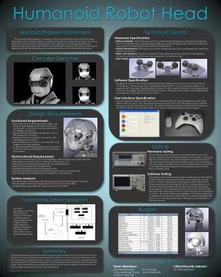
Simulation Tools for a Real Humanoid Robot. Pedro Ferreira 1 Filipe M. T. Silva 1 Vítor M. F. Santos 2. 1 Department of Electronics and Telecommunications 2 Department of Mechanical Engineering University of Aveiro , PORTUGAL. Overview. Humanoid overview Inclinometers

E N D
Simulation Tools for a Real Humanoid Robot Pedro Ferreira1 Filipe M. T. Silva1 Vítor M. F. Santos2 1 Department of Electronics and Telecommunications 2 Department of Mechanical Engineering University of Aveiro, PORTUGAL
Overview • Humanoid overview • Inclinometers • From measure to control • High-level motion algorithms • Bipedal locomotion • Rotation • Kick • Simulation Platform • Why Matlab? • Specification and functionalities • Limitations • About Future
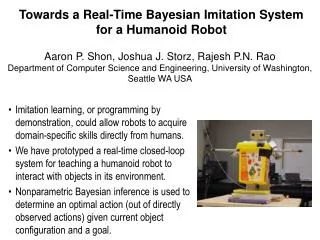
Humanoid Structure • Complete humanoid model • 22 degrees of freedom • Weight - 5 kg • Height - 60 cm • Max. width - 25 cm • Foot print - 20 8 (cm2) • Actuation • Servomotors with transmission ratio • Sensors • A vision Camera (CCD) • Servos’ position (through its internal potentiometers) • Sensitive foot to applied forces • Accelerometers/Inclinometers • Gyroscopes
Local Control • Each slave controller is made of a PIC 18F258 device with I/O interfacing • All slave units: • Connect up to 3 servomotors • Have a common base (a piggy-back unit can add I/O sensors)
Main Control RS232 Master CAN BUS Slaves 3 3 1 2 2 2 2 1 1 1 3 3 2 2 1 1 3 3 2 2 1 1 Distributed Control System • A Main Control Unit (PC): • Exchanges high-level orders and interacts with the camera. • RS-232 communication with the Distributor unit. • Distributor Unit (Master): • Interface between the Main and the Local control units. • Adapts the RS-232 to CAN commands (and vice-versa). • 8 Local Control Units (Slaves): • Control the low-level features of the several devices. • CAN bus to connect them.
Accelerometer/Inclinometer • The Accelerometer/Inclinometer used is ADXL202E (Analog Devices). • It can measure accelerations with a full-scale range of ±2G. • It can measure both dynamic acceleration (e.g., vibration) and static acceleration (e.g., gravity). • When the accelerometer is oriented so both its X and Y axes are parallel to the earth’s surface it can be used as a two axis tilt sensor with a roll and a pitch axis.
From Measure to Control • Proportional Control • Delta = error*2.5*K*1e-2; • Delta is the increment applied to servo • Error is the difference between the wanted and the measure inclination • 2.5 is the transmission ratio of servo • K*1e-2 is the real gain of controller • K vary between 10 and 50 • Higher values give rise to oscillations • Lower values has a very slow effect
Inclinometers Experiment • Experiment condition • Varying reference CoP, so the leg perform a square trajectory • Square with ~15cm width • 2 seconds to perform a edge • Controller gain was 30 • Response of inclinometer controller • Max delay = 0.797 seconds • Max error = ~9 degrees
High-level Motion Algorithms • Quasi-static Motion • All the movements are planned at a low velocity and with the CoP always on the support foot. • Locomotion • Essential algorithm based on a quasi-static walking motion which assure that the CoP is always on the support foot. • Rotation • Very important movement with tricky aspects. • Kick • Simple movement • Stair Walking • Not yet developed!
Bipedal locomotion1 • Cartesian space • Specification Parameters • Step Length • Hip height • Hip y-coordinate center position • Foot max elevation • Divided in 4 phases • Prepare • Start Step • Middle point • End of step • Prepare Next Step 1 Developed by Professor Filipe Silva
Bipedal Locomotion • Multiple Steps
Rotation1 • Cartesian and joint space motion plan • Specification Parameters • Inclination angle • Rotation angle • Hip height • Foot max elevation • Divided in 10 phases • Prepare • Rise free foot • Rotate • Align CoP with new support foot • Finish movement 1 Developed by Professor Filipe Silva
Rotation • Tricky aspect • Rotation axis isn't align with the foot • Final foot position isn’t align with the hit • Need adjust booth hit rotation joint to change the CoP to the new support foot
Kick • Specification Parameters • Inclination angle • Hip height • Foot max elevation • Divided in 4 phases • Prepare • Align CoP with new support foot • Rise free foot • Kick
Simulator TwoLegs_22dof • Motivations • Turn the interaction with the robot more easy • Need to assemble multiple work already developed like high-level movements, control adjust, communication interface… • Create an interface that allow a new user start playing with the robot in a more intuitive way • Developed on Matlab tool GUIDE
Why Matlab? • Disadvantages • Not the most flexible • Poor GUI development objects • Often must use tricks and unfriendly techniques • Slow performance • Advantages • Communications protocol already developed • Mathematical solutions (inverse and direct kinematics among others mathematical operations) • Easy integration of new work developed on Matlab • Easy and intuitive development environment • Do you speak Matlab? • A little bit! • No need to learn object oriented languages like Visual Basic, C++, C#, …
Specifications and Functionalities • Joint space motion plan • Integrate high-level movements • Plot adjusts like • Change ground dimensions and position • Put in Ball • Put in Stairs • Show CoG and CoP • Communication interface • Allow send and receive joint position for/from Humanoid robot • Trajectory plane visualization • Plot all the trajectory that the SCU will build up, with all the phases of the entire movement
Limitations • Besides the Matlab limitations already pointed… • Isn’t modeled dynamic forces • Do not detect components collision • Has no physical joint limitations • Need to know the implementation to include new high-level movements • Don’t allow to change the slaves local control • Only joint movements are allowed on the main windows
Future work • Modeling dynamic forces • Include different terrain topologies • Highlight active joint when performing a move • Develop different ways of doing the same movement • Allow dynamic adjust of PID parameters • Include a virtual image of the real Humanoid Robot • Modeling all the sensor which take in redundancy and better control • (…)