Download
1 / 28
280 likes | 448 Vues
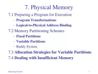
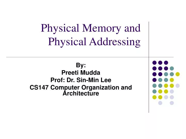
Physical Memory and Physical Addressing. By: Preeti Mudda Prof: Dr. Sin-Min Lee CS147 Computer Organization and Architecture. Agenda. Physical Memory Random Access Memory Two Types of Ram Dynamic RAM Static RAM Physical Address Word Size Byte Alignment. Physical Memory.

E N D
Physical Memory and Physical Addressing By: Preeti Mudda Prof: Dr. Sin-Min Lee CS147 Computer Organization and Architecture
Agenda • Physical Memory • Random Access Memory • Two Types of Ram • Dynamic RAM • Static RAM • Physical Address • Word Size • Byte Alignment
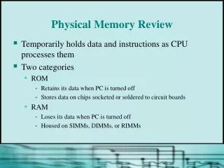
Physical Memory • Physical memory is the main memory that has direct/indirect access to CPU • Physical memory mainly consists of RAM
Random Access Memory • Random Access Memory (RAM): Any data could be accessed in a constant time regardless of its physical location. • Two Types of RAM: • DRAM – Dynamic Random Access Memory • SRAM – Static Random Access Memory
Dynamic Random Access Memory • DRAM is an integrated circuit. • Millions of transistors and capacitors are paired together to create an array of memory cells • Capacitor holds the bit information • Transistors behaves like a switch which lets the control circuitry to control the state of the memory chip by reading or changing the capacitor state.
DRAM Architecture • DRAM Chips are large and rectangular • Arrays of memory cells • Support logic- used for reading and writing data in arrays • Refresh Circuitry- maintain the integrity of the stored data by periodically refreshing the memory cells
http://www.cs.duke.edu/courses/fall98/cps104/lectures/week10-l2/sld024.htmhttp://www.cs.duke.edu/courses/fall98/cps104/lectures/week10-l2/sld024.htm
DRAM • Memory cell represents single bit data (logic 1/logic 0) • Cells are imprinted on silicon wafer • Array of columns (bitlines) • Array of rows (wordlines) • Intersection of bitline and wordline is the address of the memory cell
Support Circuitry • Sense amplifiers: Amplifies signal or charge detected on the memory cell • Address logic: Select rows and columns • Row Address Select(RAS) and Column Address Select(CAS): Latch and resolve the row and column addresses. It initiates or terminates the read/write operation
Support Circuitry • Read /Write circuitry: Store or read the information in the memory cell • Internals Counters: Keep track of the refresh sequence or initiate refresh cycle • Output Enable logic: Prevents the data from displaying it unnecessarily.
Row Address Strobe (RAS): Latch row address and initiate the memory cycle. It is required at the beginning of every operation. To enable RAS the voltage transition should be from high to low voltage. RAS is an active low and it should maintain low voltage as long as RAS is required Complete memory cycle: RAS must active for minimum amount time and also inactive for minimum amount of time. Column Address Strobe: Initiate Read/Write Operation CAS must be active before RAS for refresh cycle. DRAM Read timing
DRAM Timing • Write Enable(WE): • Write enable signal used to choose for read/write operation. • Low voltage-level signifies a write operation • High-voltage level signifies a read operation. • Output Enable (OE): • This control signal is used to prevent displaying the output while read operation. • The control signal is grounded when write operation is selected. • Data IN/OUT(DQs): • DQ pins used for input and output
http://www.cs.duke.edu/courses/fall98/cps104/lectures/week10-l2/sld024.htmhttp://www.cs.duke.edu/courses/fall98/cps104/lectures/week10-l2/sld024.htm
http://www.cs.duke.edu/courses/fall98/cps104/lectures/week10-l2/sld024.htmhttp://www.cs.duke.edu/courses/fall98/cps104/lectures/week10-l2/sld024.htm
Static RAM • Type of semiconductor memory • No need to refresh frequently • Uses six MOFETS to store each memory bit • Size: SRAM has m address lines and n data lines: 2^m words.
SRAM • Three different states: • Standby: The circuit is idle • Reading: Reading the data which has been requested • Writing: Writing the data on to the memory
SRAM http://www.cs.duke.edu/courses/fall98/cps104/lectures/week10-l2/sld016.htm
SRAM • Reading: • WE_L is dis-asserted (H), OE_L is asserted (L) • D: data output pin • Writing: • WE_L is asserted (L) where as OE_L is dis-asserted (H). • D: Data input pin. http://www.cs.duke.edu/courses/fall98/cps104/lectures/week10-l2/sld018.htm
Physical Address • Physical address is a memory address that is stored in the form of binary number • It is electronically represented on the computer address bus circuitry • Through this data bus is enabled to access particular storage from the main memory cell
Physical Memory and Word Size • Bits of physical memory are divided into blocks of N bits • Terminology • – Group of N bits is called a word • – N is known as the width of a word or the word size
Physical Memory Addresses • Each word of memory is assigned a unique number known as a physical memory address • Programmer imagines physical memory to be an array of words • Note: entire word must be transferred
Choosing A Word Size • Larger word size • Implemented with more parallel wires • Results in higher performance • Higher cost • Note: architect usually designs all parts of computer to use • one size for: • Memory word • Integer (general-purpose registers)
Byte Addressing • View of memory presented to processor • Each byte of memory assigned an address • Convenient for programmers • Underlying memory can still use word addressing
Translation Between Byte And Word Addresses • Performed by intelligent memory controller • CPU can use byte addresses (convenient) • Physical memory can use word addresses (efficient)
Byte Alignment • Refers to integer storage in memory • In some architectures – Integer in memory must correspond to word in underlying physical memory • In other architectures – Integer can be unaligned, but fetch and store operations are much slower
Memory Size And Address Space • Size of address limits maximum memory • Example: 32-bit address can represent • 2^32 = 4,294,967,296 • unique addresses • Known as address space • Note: word addressing allows larger memory than byte addressing
Resources • Physical Memory: • IBM article “Understanding DRAM operation” • CS-Duke Lecture notes: Memory Systems • Wikipedia • Howstuffworks website • Physical Address: • http://www.eecs.wsu.edu/~hauser/teaching/Arch-F07/handouts/Chapter10.pdf • Wikipedia