Download
1 / 28
370 likes | 640 Vues
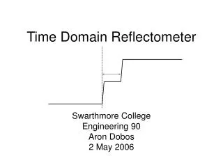
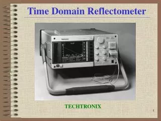
Optical Time Domain Reflectometer. Piotr Turowicz Poznan Supercomputing and Networking Center piotrek @ man.poznan.pl 9-10 October 2006. Link Characterization Using the OTDR OTDR General Theory. What is an optical time-domain reflectometer (OTDR)? Single-ended measurement tool

E N D
Optical Time Domain Reflectometer Piotr Turowicz Poznan Supercomputing and Networking Center piotrek@man.poznan.pl 9-10 October 2006
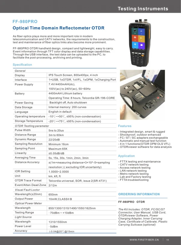
Link Characterization Using the OTDROTDR General Theory • What is an optical time-domain reflectometer (OTDR)? • Single-ended measurement tool • Provides a detailed picture of section-by-section loss • Operates by sending a high-power pulse of light down the fiber and measuring the light reflected back • Uses the time it takes for individual reflections to return to determine the distance of each event • Measures/characterizes: • Fiber attenuation • Attenuation example (new G.652.C fibers) • 0.33 dB/km at 1310 nm (0.35 dB/km for worst case) • 0.21 dB/km at 1490 nm (0.27 dB/km for worst case) • 0.19 dB/km at 1550 nm (0.25 dB/km for worst case)
Measures/characterizes: • Reflection and optical loss caused by every event in the link • Connectors • Splices • Fiber ends • Detectable faults • Misalignments and mismatches • Dirt on connector ferrules • Fiber breaks • Macrobends Link Characterization Using the OTDROTDR General Theory
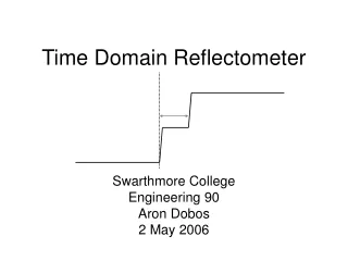
OTDR Basic Principles OTDR Basic Principles An OTDR sends short pulses of light into a fiber. Light scattering occurs in the fiber due to discontinuities such as connectors, splices, bends, and faults. An OTDR then detects and analyzes the backscattered signals. The signal strength is measured for specific intervals of time and is used to characterize events. The OTDR to calculate distances as follows: Distance = c/n * t/2 c = speed of light in a vacuum (2.998 x 10⁸ m/s) t = time delay from the launch of the pulse to the reception of the pulse n = index of refraction of the fiber under test (as specified by the manufacturer)
OTDR Basic Principles An OTDR uses the effects of Rayleigh scattering and Fresnel reflection to measure the fiber's condition, but the Fresnel reflection is tens of thousands of times greater in power level than the backscatter. Rayleigh scattering occurs when a pulse travels down the fiber and small variations in the material, such as variations and discontinuities in the index of refraction, cause light to be scattered in all directions. However, the phenomenon of small amounts of light being reflected directly back toward the transmitter is called backscattering. Fresnel reflections occur when the light traveling down the fiber encounters abrupt changes in material density that may occur at connections or breaks where an air gap exists. A very large quantity of light is reflected, as compared with the Rayleigh scattering. The strength of the reflection depends on the degree of change in the index of refraction.
Link Characterization Using the OTDROTDR General Theory • Reflectometry theory • The OTDR launches short light pulses (from 5 ns to 20 µs) • Measuring the difference between the launching time and the time of arrival of the returned signal, it determines the distance between the launching point and the event. • The OTDR uses the IOR of the fiber under test to accurately calculate the distance (speed of light in fiber is different than in the air)
Link Characterization Using the OTDROTDR General Theory • Rayleigh backscattering • Comes from the fiber’s “natural” reflectiveness • The OTDR uses the Rayleigh backreflections to measure fiber attenuation (dB/km) • Backreflection level around -75 dB • Higher wavelengths are less attenuated by the Rayleigh backscattering
Link Characterization Using the OTDROTDR General Theory • Fresnel backreflections • Come from abrupt changes in the IOR(e.g., glass/air) • - Fiber breaks, mechanical splices, bulkheads, connectors • Show as a “spike” on the OTDR trace • UPC reflection is typically –55dB; APC is typically –65dB (as per ITU) • Fresnel reflections are approximately 20 000 times higher than fiber’s backscattering level • Create a “dead zone” after the reflection
Link Characterization Using the OTDROTDR General Theory • Distance: corresponds to the distance range of the fiber span to be tested according to the selected measurement units • Pulse: corresponds to the pulse width for the test. A longer pulse allows you to probe further along the fiber, but results in less resolution. A shorter pulse width provides higher resolution, but less distance range. • Time: corresponds to the acquisition duration (period during which results will be averaged). Generally, longer acquisition times generate cleaner traces (long-distance traces) because as the acquisition time increases, more of the noise is averaged out. This averaging increases the signal-to-noise ratio (SNR) and the OTDR's ability to detect small events.
Link Characterization Using the OTDROTDR General Theory Simplified OTDR trace
Link Characterization Using the OTDROTDR General Theory • Loss in fiber is wavelength-dependent http://www.porta-optica.org
Link Characterization Using the OTDR Limitations • Event dead zone • Dead zones only affect reflective events • The event or reflective dead zone represents the minimum distance between the beginning of a reflective event and the point where a consecutive reflective event should clearly be localized. http://www.porta-optica.org
Link Characterization Using the OTDR Limitations • Attenuation dead zone • The attenuation or non-reflective dead zone is the minimum distance after which a consecutive reflective or non-reflective event and attenuation measurement can be made. http://www.porta-optica.org
Link Characterization Using the OTDR Merged Events • If the spacing between two events is shorter than the attenuation dead zone but longer than the event dead zone, the OTDR will show “merged events”. http://www.porta-optica.org
Pulse Width vs. Dead Zonesand Dynamic Range Short pulses give a higher resolution but a shorter dynamic range: http://www.porta-optica.org
Echoes on OTDR Traces http://www.porta-optica.org
Echoes on OTDR Traces http://www.porta-optica.org
Link Characterization Using theOTDRTesting Techniques • Launch cables • A launch cable is recommended if the user wants to characterize the first or last connector of an optical link. • It allows the OTDR to have a power reference before and after the connector in order to characterize it. • Standard available lengths vary from 200 meters to 1500 meters http://www.porta-optica.org
Link Characterization Using theOTDRTesting Techniques Without a pulse suppressor box http://www.porta-optica.org
Link Characterization Using theOTDRTesting Techniques Four-point events: loss measurement http://www.porta-optica.org
Link Characterization Using theOTDRTesting Techniques • The least-square approximation (LSA) method • The least-square approximation (LSA) method measures the attenuation(loss/distance) between two points by fitting a straight line to thebackscatter data between markers A and B. • The LSA attenuationcorresponds to the difference in power (dB) measured betweentwo points. http://www.porta-optica.org
Link Characterization Using theOTDRTesting Techniques Two-point sections: loss measurement http://www.porta-optica.org
Link Characterization Using theOTDRTesting Techniques Two-point sections: attenuation measurement http://www.porta-optica.org
Link Characterization Using theOTDRTesting Techniques Acquisition parameter settings http://www.porta-optica.org
Link Characterization Using theOTDRTesting Techniques To take acqusition just press START http://www.porta-optica.org
References http://www.porta-optica.org