Download
1 / 26
260 likes | 371 Vues
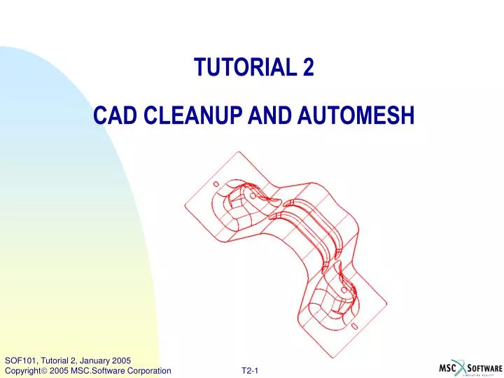
TUTORIAL 2 CAD CLEANUP AND AUTOMESH. Note: As in the other tutorials, all menu items that need to be selected will be preceded

E N D
TUTORIAL 2 CAD CLEANUP AND AUTOMESH
Note: As in the other tutorials, all menu items that need to be selected will be preceded by a maroon right arrow: >User action. Mouse buttons are indicated as follows: -- 1B = First (left) button -- used for selecting items-- 2B = Second (middle) button -- used for "OK"-- 3B = Third (right) button -- used for View Manipulation & pop-up menusNormally 1B is used, unless otherwise. Table Of Contents SectionPage Step1. Import Geometry from an IGES file. 3 Step2. Explore Geometry Graphics Display Options. 4 Step3. Use Stitch Surface Command.. 6 Step4. Extract Mid-Surface. 8 Step5. Suppress Entities .(Curves) 9 Step6 . Suppress Entities .(Vertices.) 10 Step7 . Force Suppression. 11 Step8 . Use of (Un)Suppress One Command. 13 Step9 . Trim Surfaces. 14 Step10. Use Auto Mesh. 16 Step11. Control Mesh Size And Shape. 17 Step12. Create Washer Elements Around Hole. 19 Step13. Create Hole On CAD Geometry. 21 Step14. Use Quality Check Command. 22 Step15. Use Enhance Quality Command. 23
Step1. Import Geometry from an IGES file. c b • Setup the I/O options so that the MSC.SOFY IGES translator recognizes and translates appropriate IGES entities. • From the Top Bar (select) >Options >I/O Opts >IGES Opts >IGES Input Opts. • Pull down the >Detect System menu to set it to >Auto Detect. • Select >EXIT to Exit this Pop-up. • Select >File Menu >Import >IGES option. • In the file dialog box - go to the directory (in your home directory) .../SOFY_MASTER2/DEMOS/TUTORIALS/IGES and open the file >Bracket.igs. • In the CVP View menu, set the view to >Right-Frt . g
Step2. Explore Geometry Graphics Display Options. b • Zoom in at the bottom right corner of the part. >View Manip >Win.Zoom. • Note that the part is a sheet metal bracket with solid geometry and certain thickness to it. • Bottom block - > select - >Geom-Grafix menu and "tear-off" the menu by clicking on the dashed line at the top. • To see the surfaces better, select >Face On from the menu, or clicking the icon on the toolbar. • Change the color of the part: Using 3rd mouse button (3B), select the part in Collection block (3B)>LEV_1. • From the sub-menu select (1B)>Change Color to light Blue. c d f e
Step2. Explore Geometry Graphics Display Options. (Cont’d) • Select >FILL, >PLOT from CVP view menu to display the full part in the canvas. • Get a feel for the geometry by clicking through some of the menu items in >Geom-Grafix. • Try all the options under “Edge Color:" (>Body Color, >Connectivity Color, >Part Color, and >Other Color). • Now, try the options in the "Face Color" part of the menu( >Body Color, >Part Color, and >Other Color) • Notice how the display changes as you try different options.
a Step3. Use Stitch Surface Command. Stitch Surface • First Assign Current part:- 1. Select -> Type -> Part in Collection Menu. 2. Use (2B) to select > LEV_1-1 part. LEV_1 appears next to "Curr:" at the top of CVP block. (As you create new geometry and elements, they will go into the Current part.) Part consists of a patchwork of small surfaces. Stitch these surfaces together, with a user defined stitch tolerance, to have a continuous part surface. b. In order to clearly see the effects of the stitching operation:- Select >Geom-Grafix -> Edge Color - >Conn.Color. Select >Geom-Grafix >Faces Off. b
Note that the part edge color changes to GREEN indicating that all the surface patches got stitched and that the edges are shared Step3. Use Stitch Surface Command.(Cont’d) c d c. Turn ON: Geom-Grafix >Boundary Edges Geom-Grafix >Manifold Edges Geom-Grafix >Suppressed Edge. d. From Top Menu Bar Select >Geometry >Stitch or Click >Stitch icon from Toolbar • Select from Pick menu > Sheet Bodies>click on >All button, at bottom of CVP block. (The part gets highlighted in the canvas.) g. Confirm the selection with >Done. h. Enter the stitch tolerance (say 0.5) in the pop up panel, and confirm. d h g
The outer edges and holes change to Red color, indicating them as boundary edges, now that the top and bottom surfaces have been removed, leaving only a single mid-surface . Step4. Extract Mid-Surface. Now let us extract the Mid-surface of the part. a. Select >Geometry >Extract Surface. Or click Extract Surface >icon on toolbar. (Note that the Pick menu at lower right changes to reflect the current command.) b. Pick menu -> Select >Mid Surface and Check the box for >Delete Solid. (This will delete the solid geometry, upon completion of the Mid surface extraction. ) c. Select all displayed solid bodies: Pick Menu >All and Finalize the selection with >Done. • Take a closer look at the bottom right corner. :- >ViewManip >Win.Zoom. (Note that the mid surface of the part has been extracted.) e. Select Geom-Grafix >Faces On. f. Then, Click >View >FILL to fill the part in the canvas. g. Use ViewManip > DynamicRotation and Zoom features to get a good look at the stitched midsurface of the part.
Suppressed edges are displayed now in BLUE color. The manifold edges are highlighted in GREEN color and the boundary in RED color. Step5. Suppress Entities .(Curves) b c Suppress Entities (Curves, those are not required for meshing of the part.) a. For best viewing :- 1.Select >Geom-Grafix > turn >Faces Off. 2.View back to >Right-Frt. b. Select >Geometry>(Un)Suppress Entity or Click >(Un)Suppress Many icon. c. On Pick menu -> Select >Curves d. Select >B.A in the Pick panel. e. Enter > 15 degrees in the popup panel ,confirm the selection. f. Select > All from Pick Block. g. Confirm with >D (Done) at bottom of Pick block. d e f g
Step6. Suppress Entities .(Vertices.) b Suppress Entities (Vertices, those are not required for meshing of the part.) • From Geom-Grafix -> turn ON: >Hard Points and >Suppressed Points. • Geometry > (Un)Suppress Entity command. • Select >Vertices >All in the pick panel. • Vertices get highlighted in the canvas. • Confirm with >D (Done) at bottom of Pick block,to suppress the highlighted vertices. c e d
Step7. Force Suppression. Force Suppression • There may still be some small features that are not Suppressed. Let us suppress some of the entities with Force Suppression. • Select View Manip. >Dyn.Rot and View Manip. >Window Zoom to obtain a view like the picture shown. c. Check the box for >Force Suppression and d. Select > Curves from the Pick block. e. Select View Manip. > Window Zoom f. Select >curves that are to be suppressed. g. Then while the mouse is still in the canvas, click the middle mouse button. (>2B) or Click >D button at bottom of Pick Block. b f c d
Step7. Force Suppression.(Cont’d) c Now try picking curves by refine pick option. • Select >D on left side of Pick block. • Extended Pick Dialog panel pops up. • Change from >Default to >From Vertex. Do not close the "Extended Pick Dialog" window until completing the next step. e. Pick curves by selecting on the >vertex which joinsthree curves as shown in fig. f. This allows selection of multiple curves which share a given vertex. g. Repeat for 2nd set of curves. h. Confirm the selected curves with >(2B). i. The forced suppressed curves are now shown in BLUE. j. Exit out of the Suppress Entity command by clicking >Ex (Exit) at bottom right corner . d i e
Step8. Use of (Un)Suppress One Command. c Let's try a similar command that takes advantage of part symmetry. • Select>(Un)Suppress One icon from Toolbar. • Select >curves at the pick entity (default) and make sure the >Symmetry box is checked • Select a few more small curves for suppression from the canvas. (Note how this command is a bit different from (Un)Suppress Many command.) e. This is a toggle command and entities are immediately suppressedupon picking them. f. If selected again, the entities will be returned to Un-suppressed state. g. Also note that any symmetrical entities are also suppressed on the other side of the part. h. Rotate the model >View.Manip >Dyn.Rot to get a clear view of the other end of the part. i. Pick curves to be suppressed on the other end of the model. b d
Step9. Trim Surfaces. d Trim Surfaces • Set >Suppressed Edges >Off to remove suppress edges from display. b. Set >Suppressed Points >Off. c. Zoom and rotate the model to obtain the view shown. d. Select >Geometry >Trim Surface By Locs (or select icon from toolbar) e. Pick entity type of Vertices (default). f. Trim the geometry by selecting end point >vertices defining the new curve to be placed on the surface. g. Confirm with >2B to complete the trim operation. h. In a similar fashion, trim the surface at a second location. e f
Step9. Trim Surfaces.(Cont’d) j. Return to >Geometry >(Un)Supress Entity to suppress the original small k. Rotate the model, then trim and suppress curves at the other end of the model in a similar fashion. l. Set >Geom-Grafix >Boundary Edges On Geom-Grafix >Manifold Edges On Geom-Grafix >Face Color >Part Color Geom-Grafix >Edge Color >Connectivity Color The geometry is now cleaned up and ready for meshing. Save the model as MSC.SOFY database >File >Save As >...\Bracketclean.sof
Step10. Use Auto Mesh. • Let us proceed to generate the finite element mesh using the automesher. • Select >Mesh Menu >Automesh, or Pick >Automesh icon from Mesh toolbar. MSC.SOFY can automatically decide the best meshing method based on geometry. in Pick panel. c. In Pick Panel Select >Auto Decide Select >Mixed (Quad Dominant) in Pick panel. Select >Surfaces to be meshed. d. In this case select >All to mesh all displayed surfaces in the canvas. e. Confirm with >D (Done). • The Automesher successfully generates the mesh. g. Select >Geom-Grafix >Face Off • Select >FE-Grafix >Fill+Edges • Review the mesh quality by rotating and zooming into the model for a visual inspection. b c f d
Step11. Control Mesh Size And Shape. e f Let us take a closer look at mesh quality and update the mesh by making certain changes in the Mesh controls. • Set >View >Left-Frt • Select >View.Manip >Win.Zoom zoom in to the small hole in the foreground (left side of part). • Geom-Grafix >Mesh Points On. • Now revise the mesh so there will be 4 nodes around the hole, instead of 3. • Select >Mesh Menu >Mesh Size. • In Pick panel, change >Pitch to >Number • Select >Curves from Pick menu • Then on the canvas 1. Select>curve that defines the hole. 2. Confirm with <(2B). 3. Then in the pop-up menu, "Enter # Segments:" 4, then >OK. i. Notice that any part of the mesh that is affected by the revised number of segments around the hole, is immediately removed from the display. g h i
Step11. Control Mesh Size And Shape. (Cont’d) j j. Select >Mesh Menu >Update Mesh. Notice the revised element distribution around the hole. • Now let us try to refine mesh around the slotted hole at the other end of the part. • View block >Plan view • Select >View.Manip >Win.Zoom >ViewManip.>Dyn.Rot to get a good look at the slotted hole at the other end of the model. n. Set >Geom-Grafix >Hard Points ON. >Geom-Grafix >MeshPoints ON. o. Now create a hard point on the hole to seed the nodes in a desired fashion: 1. Select >Geometry >Create Hard Points. 2. Select >Pt. on Curve from pick menu. 3. Select >curve that defines the hole followed by a >new point on the curve. 4. For instance select a point on the hole nearest the edge of the part. 5. Click >Exit button in Pick block. p. To redefine the number of points around the elliptical hole: 1. Select >Mesh Menu >Mesh Size, or Mesh Size icon. 2. Pick menu> Curve (Entity type ). 3. Select the hole edge. 4. Confirm the selection with >(2B). 5. Enter # Segments >6 and >OK, on the pop up menu . • Update the mesh : Select >Mesh Menu >Update Mesh. Later on we will make some further improvements to the mesh quality. o p.5
Step12. Create Washer Elements Around Hole. b Now let us look at a quick way to create a washer around a hole. • Set >View >Left-Frt • Select >View.Manip >Win.Zoom to zoom in on the hole on the top of the part, where we will create a washer (concentric rings of elements). c. Toolbar> Geometry Cleanup menu >Create Washer icon. d. On canvas, Select >curve at the hole where washer is desired. e. Confirm with >(2B). f. Enter width (say 5 mm) of the washer in the pop up menu. c d f
Step12. Create Washer Elements Around Hole. (Cont’d) g i • Toolbar > Select >Link Curves. • It will prompt to pick Master Link Curve • Select >hole from canvas. • For Dependent curve : Choose the newly created >washer curve. k. Click >Ex at lower right corner to exit the Link Curves command. By linking the curves, the mesh quality is better controlled. l. Select >Mesh Size icon from Toolbar. m. Pick Menu > Curves is highlighted n. Select >hole from the canvas. o. Confirm curve selection with >(2B). p. In the pop up menu, 1. Enter # Segments: 6. 2. Click >OK. • Click >Ex in Pick block to exit the command. • Use the >Update Mesh icon on the Toolbar to update the mesh at the washer. j l p m q
Step13. Create Hole On CAD Geometry. b a. Set >View >Left-Frt. and Zoom in to corner where hole is to be placed. b. Select >Mesh Menu >Create Hole (or select icon from Toolbar). • Select >Pt. on Surface from Pick menu (default). • Pick >surface from canvas, • Select >point on the surface at which hole will be created. f. Confirm with (2B). g. Enter the radius of the hole (say 12 mm) in the pop up menu. h. Select >Mesh Menu >Mesh Size to define number of nodes on the hole, as done above. If desired, create a curve defining a washer around the hole, and link the two curves, as above. i. Select >Mesh Menu >Update Mesh (or select icon) to recreate the mesh . j. >Exit any active commands, k. Click >F4 key to clear the unreferenced nodes. c g
Step14. Use Quality Check Command. a Now let us check and Enhance the Quality of the mesh. • Turn off all geometry by un-checking the box in Bottom block. >Fill the canvas. • Select >FE-Grafix >Fringes On to quickly look at the mesh quality • Default display is the Quality Index, which is a weighted average of several quality criteria. d. Pink color indicates the elements that failed in one or more quality checks. b
Step15. Use Enhance Quality Command. • To automatically enhance the mesh quality Select >Element >Quality >Enhance Quality. • In the pick menu >Select >All to select all displayed elements • Confirm with >Done. • In the dialog box, use the default settings, and Select >Enhance to proceed. • The progress of the operation will be displayed in the lower left corner of your screen. • When the quality enhancement is completed you can see the improved element quality in the fringes. • Any elements that could not be fixed in the specified number of passes are highlighted. a b c Detailed Quality checks and Automatic Mesh Quality Enhancement are discussed in Tutorial 5. d
Yes, We finished Tutorial 2. Time for a break.!!!!