Download
1 / 35
360 likes | 479 Vues
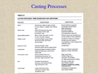
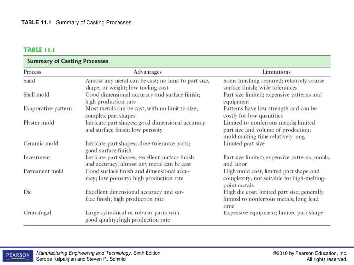
TABLE 11.1 Summary of Casting Processes.

E N D
FIGURE 11.1 (a) Typical gray-iron castings used in automobiles, including the transmission valve body (left) and the hub rotor with disk-brake cylinder (front). Source: Courtesy of Central Foundry Division of General Motors Corporation. (b) A cast transmission housing. (c) The Polaroid PDC-2000 digital camera with an AZ191D die-cast, high-purity magnesium case. (d) A two-piece Polaroid camera case made by the hot-chamber die-casting process. Source: (c) and (d) Courtesy of Polaroid Corporation and Chicago White Metal Casting, Inc.
FIGURE 11.2 Outline of production steps in a typical sand-casting operation.
FIGURE 11.3 Schematic illustration of a sand mold, showing various features.
FIGURE 11.4 A typical metal match-plate pattern used in sand casting.
FIGURE 11.5 Taper on patterns for ease of removal from the sand mold.
FIGURE 11.6 Examples of sand cores, showing core prints and chaplets to support the cores.
FIGURE 11.7 Vertical flaskless molding. (a) Sand is squeezed between two halves of the pattern. (b) Assembled molds pass along an assembly line for pouring. (c) A photograph of a vertical flaskless molding line. Source: Courtesy of American Foundry Society.
FIGURE 11.8 Schematic illustration of the sequence of operations for sand casting. (a) A mechanical drawing of the part is used to generate a design for the pattern. Considerations such as part shrinkage and draft must be built into the drawing. (b–c) Patterns have been mounted on plates equipped with pins for alignment. Note the presence of core prints designed to hold the core in place. (d–e) Core boxes produce core halves, which are pasted together. The cores will be used to produce the hollow area of the part shown in (a). (f) The cope half of the mold is assembled by securing the cope pattern plate to the flask with aligning pins and attaching inserts to form the sprue and risers. (g) The flask is rammed with sand, and the plate and inserts are removed. (h) The drag half is produced in a similar manner with the pattern inserted. A bottom board is placed below the drag and aligned with pins. (i) The pattern, flask, and bottom board are inverted, and the pattern is withdrawn, leaving the appropriate imprint. (j) The core is set in place within the drag cavity. (k) The mold is closed by placing the cope on top of the drag and securing the assembly with pins. The flasks are then subjected to pressure to counteract buoyant forces in the liquid, which might lift the cope. (l) After the metal solidifies, the casting is removed from the mold. (m) The sprue and risers are cut off and recycled, and the casting is cleaned, inspected, and heat treated (when necessary). Source: Courtesy of Steel Founders’ Society of America.
FIGURE 11.9 The shell-molding process, also called the dump-box technique.
FIGURE 11.10 Sequence of operations in making a ceramic mold. Source: Metals Handbook, Vol. 5, 8th ed.
FIGURE 11.11 Schematic illustration of the expendable-pattern casting process, also known as lost-foam or evaporative-pattern casting.
FIGURE 11.12 (a) Metal is poured into a mold for lost-foam casting of a 60-hp, three-cylinder marine engine; (b) finished engine block. Source: Mercury Marine.
FIGURE 11.13 Schematic illustration of the investment-casting (lost-wax) process. Castings produced by this method can be made with very fine detail and from a variety of metals. Source: Courtesy of Steel Founders’ Society of America.
FIGURE 11.14 Investment casting of an integrally cast rotor for a gas turbine. (a) Wax pattern assembly. (b) Ceramic shell around wax pattern. (c) Wax is melted out and the mold is filled, under a vacuum, with molten superalloy. (d) The cast rotor, produced to net or nearnet shape. Source: Courtesy of Howmet Corporation.
FIGURE 11.15 Cross section and microstructure of two rotors: (top) investment cast; (bottom) conventionally cast. Source: Courtesy of ASM International.
FIGURE 11.16 Manufacture of total knee replacements. (a) The Zimmer NexGen mobile-bearing knee (MBK); the femoral portion of the total knee replacement is the subject of the case study. (b) Assembly of patterns onto a central tree. (c) Dipping of the tree into slurry to develop a mold from investment. (d) Pouring of metal into a mold. Source: Courtesy of M. Hawkins, Zimmer, Inc.
FIGURE 11.17 Progression of the tree. (a) After assembly of blanks onto the tree; (b) after coating with investment; (c) after removal from the mold. Source: Courtesy of M. Hawkins, Zimmer, Inc.
FIGURE 11.18 Schematic illustration of the vacuum-casting process. Note that the mold has a bottom gate. (a) Before and (b) after immersion of the mold into the molten metal. Source: After R. Blackburn.
FIGURE 11.19 Schematic illustration of the hot-chamber die-casting process.
FIGURE 11.20 Schematic illustration of the cold-chamber die-casting process. These machines are large compared to the size of the casting, because high forces are required to keep the two halves of the dies closed under pressure.
TABLE 11.3 Properties and Typical Applications of Some Common Die-casting Alloys
FIGURE 11.21 Various types of cavities in a die-casting die. Source: Courtesy of American Die Casting Institute.
FIGURE 11.22 (a) Schematic illustration of the centrifugal-casting process. Pipes, cylinder liners, and similarly shaped parts can be cast with this process. (b) Side view of the machine.
FIGURE 11.23 (a) Schematic illustration of the semicentrifugal casting process. Wheels with spokes can be cast by this process. (b) Schematic illustration of casting by centrifuging. The molds are placed at the periphery of the machine, and the molten metal is forced into the molds by centrifugal force.
FIGURE 11.24 Sequence of operations in the squeeze-casting process. This process combinesthe advantages of casting and forging.
FIGURE 11.25 Methods of casting turbine blades: (a) directional solidification; (b) method to produce a single-crystal blade; and (c) a single-crystal blade with the constriction portion still attached. Source: (a) and (b) After B.H. Kear, (c) Courtesy of ASM International.
FIGURE 11.26 Two methods of crystal growing: (a) crystal pulling (Czochralski process) and (b) the floating-zone method. Crystal growing is especially important in the semiconductor industry. (c) A single-crystal ingot produced by the Czochralski process. Source: Courtesy of Intel Corp.
FIGURE 11.27 (a) Schematic illustration of melt spinning to produce thin strips of amorphous me tal. (b) Photograph of nickel-alloy production through melt spinning. Source: Courtesy of Siemens AG.
FIGURE 11.28 Two types of melting furnaces used in foundries: (a) crucible and (b) cupola.