Download
1 / 10
100 likes | 282 Vues
DPM Design. MWD / CSOP Engineering Design and Hydrologic Considerations 30 August 2007. Overview. WCA-3A to WCA-3B Conveyance Features 1992 MWD GDM 2006 CSOP TSP CSOP Controllable Conveyance Features DPM Design Available Engineering Data DPM Design Available Hydrologic Data.

E N D
DPM Design MWD / CSOP Engineering Design and Hydrologic Considerations 30 August 2007
Overview • WCA-3A to WCA-3B Conveyance Features • 1992 MWD GDM • 2006 CSOP TSP • CSOP Controllable Conveyance Features • DPM Design Available Engineering Data • DPM Design Available Hydrologic Data
WCA-3A to WCA-3B Conveyance • 1992 MWD GDM • 3 identical gated culvert structures (S-345s) • Each with three 72-inch CMP or concrete pipes with manually-operated slide gates • Design discharge: 500 cfs for HW of 9.4 and TW of 7.9 • Discharge channels (30-foot bottom width) with containment levees between L-67A and L-67C and 1000-foot tie-back levees beyond L-67C levee • Discharge channels include L-67C gaps and canal fill • S-349 structures with boat by-pass south of each S-345s • S-355s design discharge: • 1000 cfs at each structure at HW of 9.2 and TW of 8.9
WCA-3A to WCA-3B Conveyance • 2006 CSOP Tentatively Selected Plan • 3 identical “hybrid” structures • Stop-log riser structure (AVAILABLE FOR DPM) • Five box culverts (10 ft width x 8 ft height x 16 ft length) • Inflow control elevation set at ground surface elevation • Structures able to be closed • Passive Weir Structure (NOT AVAILABLE FOR DPM) • Six box culverts (10 ft wide x 8 ft height x 16 ft length) • Sheet-pile passive weirs upstream of box culverts • Upstream approach channel (220 ft width, 90 ft length) • Downstream spreader canal (800 ft length) • S-349s replaced by 100 ft length boat plugs • S-355s as constructed, based on 1992 GDM
CSOP Controllable Conveyance • DPM conveyance from WCA-3A to WCA-3B limited to stop-log riser structures due to system constraints, including Tamiami Trail • Design information for L-67A conveyance structures is based on rating curves: f ( HW, TW, friction losses ) • Frequency and timing of various discharge volumes can be estimated based on review of historic water stages • IOP operations anticipated during DPM: started June 2002 • Actual DPM discharge volumes are uncertain and will be driven by climatologic conditions, since conveyance structures are gravity-driven
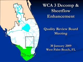
Available historical water stage data: WCA-3A: Site 64 L67 “pocket”: Site 69 WCA-3B: Site 71 Notes: Transect is located between proposed northern and middle L67A structures Site 71 influenced by remaining L67C gap Existing Canal / spoil material 2.5 miles north of L-29 must be considered for DPM CSOP Controllable Conveyance
CSOP Controllable Conveyance Peak dry or wet Season head gradient (no friction losses) HW