Download
1 / 120
1.22k likes | 1.52k Vues
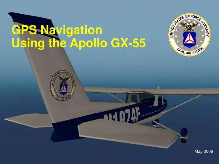
GPS Navigation Using the Apollo GX-55. May 2008. Motivation. GPS is a powerful tool for search and rescue Allows very precise search patterns Makes manageable what would otherwise be very difficult patterns Expanding square at any angle Creeping line along a course Offset route searches

E N D
GPS NavigationUsing the Apollo GX-55 May 2008
Motivation • GPS is a powerful tool for search and rescue • Allows very precise search patterns • Makes manageable what would otherwise be very difficult patterns • Expanding square at any angle • Creeping line along a course • Offset route searches • Grid searches over indistinct terrain • GPS should be our primary tool for Search and Rescue navigation • GPS is of course also very handy for general navigation
Before we begin… How does one learn to use GPS? • This presentation provides a good foundation of knowledge, but it will be forgotten quickly if not used • Hands-on practice is the only way to become proficient • Start out with the software simulator, if possible • The simulator has limitations and a few bugs, but it is worthwhile • Information on how to acquire the simulator can be found at the end of this presentation • Download the “shorthand guide” from the wing website and keep it with your mission kit • Practice with the real device in flight
Before we begin… • After you’ve had some practice, consider reviewing the GPS user manual (or study this presentation again) • When you think you have it down, try teaching someone else!
GPS Navigation Using the GX-55Course Outline This presentation is organized in six parts • Fundamentals of GPS Navigation • Introduction to using the Apollo GX-55 • Basic tasks with the GX-55 • GX-55 search patterns • Safety issues • Using the GX-55 simulator software
Part 1 – Fundamentals of GPS Navigation • How it works: The basics • Accuracy • Describing locations
How it Works – The Basics • Spaced-based system (unlike Loran or VOR) • ‘Constellation’ of 24 satellites in six orbital planes • 21 active satellites plus 3 operating spares • In “High” orbit of about 12,000 miles • Each circles the Earth about every 12 hours
How it Works – The Basics • GPS satellites transmit information • “Pseudo-random” code with time information • Satellite orbital position data • “Almanac” data • “Ephemeris” data • Updated atmospheric models • GPS receiver uses this data to figure out what time it is and what time the signals were sent
How it Works – The Basics • GPS receiver measures distance to satellites by determining the amount of time that the radio signal takes to travel from each satellite • Each distance measurement effectively defines a sphere around a satellite • Multiple satellites must be used to determine a position • Given two satellites, two sphere intersect to determine a circle • Given three satellites, a sphere and a circle intersect to determine two points • A fourth satellite can determine a positive 3D position
Accuracy • A complex question • DOD has a 66 page document describing the performance of GPS Standard Positioning Service (SPS) • The short story • Garmin states that their GPS receivers “are accurate to within 15 meters on average” • Typically about 6 to 12 Meters accuracy can be seen
Accuracy • Accuracy and reliability is actually a complex subject. There are many factors that can impact system. • Receiver errors • Atmospheric (ionosphere) errors • Solar activity (sun spots and solar storms) • Location of receiver (some parts of the Globe get better coverage than others) • Orbital errors (inaccuracies in the reported orbital position) • Poor satellite geometry (satellites lined up or bunched up) • Limited number of satellites in view • Satellite malfunctions (or satellites taken out of service) • “Multi-path” errors (radio signal reflections) • Results vary hour by hour, day by day
Accuracy • There is a substantial difference between typical accuracy and worst-case accuracy • Described as a statistic: x% had an error of y meters or less Typical 95% horizontal error results for a typical day: Errors worse than 30 meters are possible given the potential for various atmospheric conditions and receiver faults and the possibility that satellites can be taken out of service
Accuracy and“Selective Availability” • Past feature of GPS SPS that purposefully degraded accuracy of position determination for non US-military use • Civilian accuracy was typically about 100 meters under Selective Availability • SA was discontinued May 1, 2000 • Has not been used since • It's been replaced by “selective deniability,” which allows the US military to geographically designate areas in which to degrade GPS quality.
Comparing Accuracy with and without SA – A sample The plots show that SA causes 95% of the points to fall within a radius of 60.7 yards. Without SA, 95% of the points fall within a radius of 7.9 yards.
Comparing Accuracy with and without SA – Recap • Before, with 100 meter typical accuracy allowed you to identify what stadium you were in • Now with 6-12 meter typical accuracy, you can tell about which yard line you are on
Accuracy – WAAS • Wide-Area Augmentation System • Designed specifically for aviation • Commissioned by FAA in 2003 • Uses ground stations and satellites • 25 ground stations cover the entire US and parts of Canada and Mexico • Augments GPS Standard Positioning Service • Provides better integrity and accuracy • Typical accuracy of 3-5 meters horizontal, 3-7 meters vertical • Can be used for precision approaches • WAAS is not a feature of the Apollo GX-55 used by CAP
Describing LocationsA Choice to Understand • We describe latitude and longitude normally using degrees and minutes • When dealing with fractions of minutes there is, however, a choice • There are essentially two options: • One can use seconds (of which there are 60 in one minute) • One can use decimal-minutes (i.e. tenths and hundredths of a minute) • Many GPS units can be configured to display one way or the other
Describing LocationsCAP Standard Method • The standard we will use in CAP is degrees and decimal minutes • Example: 45 degrees 35.4 minutes North 93 degrees 42.2 minutes West • This is the standard way the Air Force provides coordinates to us for search and rescue • This is also the way our GX-55 normally displays position information • In CAP we will not usually use “seconds” unless working with another agency that wishes to do so.
Describing LocationsCommunicating with Others • The seconds vs. decimal minutes question is a big source of confusion even within our own ranks • Some people erroneously say “seconds” when they mean “hundredths of a minute” • Some people say “point” or “decimal” when they should have said “minutes” and “seconds” • Take nothing for granted when getting information • Be accurate and clear when giving information • Especially when working with other-agencies, triple-check all coordinates to make sure we’re all speaking the same language • The Coast Guard Auxiliary normally uses Degrees-Minutes-Seconds as their standard way of describing positions, but they will use the word “decimal” or “point” to separate the three parts of the coordinate
Describing LocationsYet Another Approach to be Aware of • Some GPS units (including the GX-55) also offer the option to display position information using Universal Transverse Mercator” (UTM) • An alternative to using degrees and minutes • Beyond the scope of this course • We will not use this
Part 2 –Introduction to using the Apollo GX-55 • Equipment overview • The controls and function/page hierarchy • Review terminology • Tour of display pages – how to read displayed information
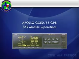
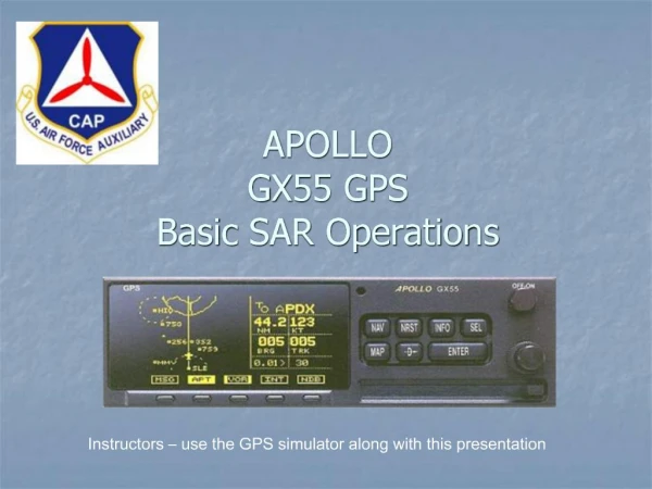
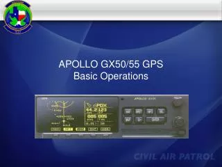
Our Equipment: Apollo GX-55 • Extensive Database • Scrolling Map Display • Search and Rescue Functions
Power Switch “Hard” keys “Smart” Keys& “annunciators” “Small”Knob “Large”Knob GX-55 Controls
Large & Small Knobs • Moving between pages • Large knob selects most main pages • Small knob selects sub pages • Different scale maps • Sub-pages in set-up areas • Entering Data • Large Knob moves cursor • Small Knob changes word or character at cursor
NAV Navigation display pages, flight plan setup, etc. MAP Map display pages NRST Pages with nearest waypoints INFO Database information pages SEL Select Make a cursor appear so you can change a value on a page When a question is being asked, make the cursor disappear, effectively responding “no” to the question Enter Complete some data entry action Also used to answer “yes” in response to a question D “Direct-To” (short-cut flight-plan from current location) Hard Keys
Function/Page Hierarchy:Getting to the screen page you want Main hierarchy: • Hard key (example: MAP) • Large Knob (example: Map Setup) • Small Knob (example: Route Line, Map Orient, & Map Reference)
Function/Page Hierarchy:Getting to the screen page you want Other paths: • Hard key (example: NAV) • Smart key (example: FPL – Flight Plan) • Large knob (example: Create new flight plan)
Smart Keys Three major uses • Page navigation • FPL – Flight plan • DB – Database • Short-cut to change values on page (without pressing SEL and turning knobs) • Clutter/de-clutter features on maps • Three-way toggles for waypoints: show waypoint icon, show icon and label, and hide
Terminology: Waypoint • A specific named location either defined by the user or defined in the instrument’s database • Database waypoints come in flavors: • Airport • VOR • NDB • Intersection (INT)
Terminology:Defining Different Directions • Desired Track / Course • Bearing • Track • Heading • Track Angle Error Note: All directions in GPS unit are magnetic
Desired Track North (magnetic) TO Waypoint Course DTK FROM Waypoint • DTK – Desired Track: course direction, direction between two waypoints
Bearing North (magnetic) TO Waypoint BRG FROM Waypoint • BRG – Bearing: direction to a waypoint
Heading North (magnetic) TO Waypoint FROM Waypoint Heading • Heading – direction the aircraft is pointed
Track North (magnetic) TO Waypoint TRK FROM Waypoint • TRK – Track: direction the aircraft is going
Track Angle Error North (magnetic) TO Waypoint Course DTK DTK TRK TAE FROM Waypoint • TAE – Track Angle Error: difference between track and desired track
Recap – Defining Different Directions North (magnetic) TO Waypoint Course BRG DTK TRK TAE FROM Waypoint Heading • DTK – Desired Track: course direction, direction between two waypoints • BRG – Bearing: direction to a waypoint • TRK – Track: direction the aircraft is going • Heading – direction the aircraft is pointed • TAE – Track Angle Error: difference between track and desired track
A Tour of Display PagesHow to Read Displayed Information • NAV ETE • Split Screen Map • Full Screen Map • More Pages
Reading the NAV ETE Display Estimated Time Remaining Value (26 minutes) TO-Waypoint Identifier (Airport DLH, Duluth) “Estimated Time Enroute” Label • Graphic Course Deviation Indicator (CDI) • Triangle at center is TO/FROM indicator (pointing up indicates “To”) • CDI “needle” is at the end of bar graph line (indicates we need to go right to get back on course) Distance off-track (0.17 NM left of course) Bearing to the TO-waypoint (017 degrees) Distance to the TO-waypoint (43.5 nautical miles)
Reading the NAV ETE Display Diamond indicates additional pages of information can be selected by turning the small knob Relative Bearing Indicator arrow points to approximate bearing relative to current track – It points in one of 8 directions
Some ‘Diamond’ NAV ETE Pages(Use small knob to move between)
FROM-side of destination waypoint TO-side of destination waypoint TOWaypoint FROMWaypoint Reading the NAV ETE Display Differences whenpast“TO waypoint” Estimated return time to the “TO-waypoint” (13 minutes) Increasing if moving away; estimated based on current ground speed Graphic CDI center triangle points down to indicate “FROM” – i.e. past the “TO-waypoint”
Reading the Split Screen Map Page To-Waypoint Identifier (Airport DLH, Duluth) Ground speed(100 Knots) Map scale(15 NM measured from top to bottom) Current track direction (014 degrees)
Reading the Split Screen Map Page Remaining distance to the TO waypoint(114 Nautical Miles) Bearing to the TO Waypoint from current position (014 degrees) Course-deviation indicator (exactly on-course or slightly left of course)
Reading the Split Screen Map Page Route-line(note map-orientation is currently North-up) Aircraft current position on map
Reading the Full Screen Map Page Bearing to the TO Waypoint from current position (017 degrees) TO Waypoint Identifier (Airport DLH, Duluth) Remaining distance to the TO waypoint(75.0 Nautical Miles) Map scale(30 NM measured from top to bottom)
Reading the Full Screen Map Page Route-line(note map-orientation is currently North-up) Waypoint Location Aircraft current position on map Waypoint Identifier
Map Clutter/De-clutter Smart Keys • Smart keys on maps are used primarily for clutter/de-clutter control • For each kind of waypoint, there is a three-way toggle • Display icon with label • Display icon without label • Don’t display • Annunciators above keys indicate current state of each option FBL (Faribault) Airport icon shown and labeled APT (airport) annunciator fully lit, so airports will be shown and labeled
Map Clutter/De-clutter Smart Keys • Smart keys on maps are used primarily for clutter/de-clutter control • For each kind of waypoint, there is a three-way toggle • Display icon with label • Display icon without label • Don’t display • Annunciators above keys indicate current state of each option Halfway VOR (icon only) VOR annunciator half-lit, so VORs will be depicted as unlabeled icons.
Map Clutter/De-clutter Smart Keys • Smart keys on maps are used primarily for clutter/de-clutter control • For each kind of waypoint, there is a three-way toggle • Display icon with label • Display icon without label • Don’t display • Annunciators above keys indicate current state of each option INT annunciator unlit, so intersections will not be depicted