Download
1 / 21
210 likes | 597 Vues
CS 162 Computer Architecture Lecture 3: Pipelining Contd. Instructor: L.N. Bhuyan www.cs.ucr.edu/~bhuyan/cs162. a d d. Sign Extend. Single Cycle Datapath (From Ch 5). M u x. a d d. 4. << 2. PCSrc. MemWrite. 25:21. Read Reg1. Read Addr. P C. Read data. Read data1.

E N D
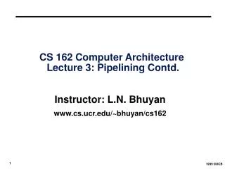
CS 162 Computer Architecture Lecture 3: Pipelining Contd. Instructor: L.N. Bhuyan www.cs.ucr.edu/~bhuyan/cs162
a d d SignExtend Single Cycle Datapath (From Ch 5) M u x a d d 4 << 2 PCSrc MemWrite 25:21 ReadReg1 Read Addr P C Readdata Readdata1 Zero ReadReg2 31:0 20:16 A L U Instruc- tion Address Readdata2 M u x MemTo- Reg WriteReg M u x Dmem Imem Regs ALU- con WriteData WriteData 15:11 M u x RegDst ALU- src RegWrite MemRead 15:0 ALUOp
Required Changes to Datapath • Introduce registers to separate 5 stages by putting IF/ID, ID/EX, EX/MEM, and MEM/WB registers in the datapath. • Next PC value is computed in the 3rd step, but we need to bring in next instn in the next cycle – Move PCSrc Mux to 1st stage. The PC is incremented unless there is a new branch address. • Branch address is computed in 3rd stage. With pipeline, the PC value has changed! Must carry the PC value along with instn. Width of IF/ID register = (IR)+(PC) = 64 bits.
Changes to Datapath Contd. • For lw instn, we need write register address at stage 5. But the IR is now occupied by another instn! So, we must carry the IR destination field as we move along the stages. See connection in fig. Length of ID/EX register = (Reg1:32)+(Reg2:32)+(offset:32)+ (PC:32)+ (destination register:5) = 133 bits Assignment: What are the lengths of EX/MEM, and MEM/WB registers
Pipelined Datapath (with Pipeline Regs)(6.2) Fetch Decode Execute Memory Write Back 0 M u x 1 IF/ID EX/MEM ID/EX MEM/WB A d d A d d 4 A d d r e s u l t S h i f t l e f t 2 R e a d n o r e g i s t e r 1 i A d d r e s s P C t R e a d c u d a t a 1 r R e a d t s Z e r o n r e g i s t e r 2 I A L U R e a d A L U 0 R e a d W r i t e A d d r e s s d a t a 2 r e s u l t 1 d a t a r e g i s t e r M M Imem Regs u u W r i t e x x d a t a 1 0 W r i t e Dmem d a t a 1 6 3 2 S i g n e x t e n d 5 69 bits 133 bits 64 bits 102 bits
RegDstALUopALUSrc Pipelined Control (6.3) • Start with single-cycle controller • Group control lines by pipeline stage needed • Extend pipeline registers with control bits W B I n s t r u c t i o n Mem W B C o n t r o l E X W B Mem MemToRegRegWrite Branch MemReadMemWrite I F / I D I D / E X E X / M E M M E M / W B
Pipelined Processor: Datapath + Control PCSrc • More work to correctly handle pipeline hazards I D / E X 0 M W B u E X / M E M x 1 C o n t r o l M W B M E M / W B E X M W B I F / I D A d d A d d 4 A d d r e s u l t Branch RegWrite S h i f t l e f t 2 ALUSrc MemWrite MemToReg n R e a d o i r e g i s t e r 1 t P C A d d r e s s R e a d c u r d a t a 1 t R e a d s n Z e r o r e g i s t e r 2 I A L U R e a d A L U Imem 0 R e a d W r i t e d a t a 2 r e s u l t A d d r e s s 1 d a t a r e g i s t e r M M Regs u u W r i t e x x d a t a Dmem 1 0 W r i t e d a t a I n s t r u c t i o n 1 6 3 2 6 [ 1 5 – 0 ] MemRead S i g n A L U e x t e n d c o n t r o l I n s t r u c t i o n [ 0 1 6 ] 2 – ALUOp 0 M u I n s t r u c t i o n x [ 1 5 – 1 1 ] 1 RegDst
Recap • if can keep all pipeline stages busy, can retire (complete) up to one instruction per clock cycle (thereby achieving single-cycle throughput) • The pipeline paradox (for MIPS): any instruction still takes 5 cycles to execute (even though can retire one instruction per cycle)
Problems for Pipelining • Hazards prevent next instruction from executing during its designated clock cycle, limiting speedup • Structural hazards: HW cannot support this combination of instructions (single memory for instruction and data) • Data hazards: Instruction depends on result of prior instruction still in the pipeline • Control hazards: conditional branches & other instructions may stall the pipeline delaying later instructions
M ALU M M Reg Reg ALU M M Reg Reg ALU ALU M M Reg Reg ALU Single Memory is a Structural Hazard Time (clock cycles) I n s t r. O r d e r M Reg Reg Load Instr 1 Instr 2 M M Reg Reg Instr 3 Instr 4 • Can’t read same memory twice in same clock cycle
EX: MIPS multicycle datapath: Structural Hazard in Memory PC Instruction Register ReadReg1 Address Memory A Readdata 1 ReadReg2 A L U Instruction or Data ALU- Out Registers B Readdata 2 WriteReg Data MemoryData Register Data
Structural Hazards limit performance • Example: if 1.3 memory accesses per instruction (30% of instructions execute loads and stores)and only one memory access per cycle then • Average CPI 1.3 • Otherwise datapath resource is more than 100% utilized Structural Hazard Solution: Add more Hardware
Speed Up Equation for Pipelining CPIpipelined = Ideal CPI + Pipeline stall clock cycles per instn Speedup = Ideal CPI x Pipeline depth Clock Cycleunpipelined ---------------------------------- X ------------------------- Ideal CPI + Pipeline stall CPI Clock Cyclepipelined Speedup = Pipeline depth Clock Cycleunpipelined ------------------------ X --------------------------- 1 + Pipeline stall CPI Clock Cyclepipelined x
Example: Dual-port vs. Single-port • Machine A: Dual ported memory • Machine B: Single ported memory, but its pipelined implementation has a 1.05 times faster clock rate • Ideal CPI = 1 for both • Loads are 40% of instructions executed SpeedUpA = Pipeline Depth/(1 + 0) x (clockunpipe/clockpipe) = Pipeline Depth SpeedUpB = Pipeline Depth/(1 + 0.4 x 1) x (clockunpipe/(clockunpipe / 1.05) = (Pipeline Depth/1.4) x 1.05 = 0.75 x Pipeline Depth SpeedUpA / SpeedUpB = Pipeline Depth/(0.75 x Pipeline Depth) = 1.33 • Machine A is 1.33 times faster
Data Hazard on Register $1 (6.4) add $1,$2, $3 sub $4, $1,$3 and $6, $1,$7 or $8, $1,$9 xor $10, $1,$11
IM ALU IM ALU IM DM Reg Reg ALU Data Hazard Solution: • “Forward” result from one stage to another • “or” OK if implement register file properly Time (clock cycles) I n s t r. O r d e r IF ID/RF EX MEM WB add $1,$2,$3 Reg Reg ALU IM DM sub $4,$1,$3 DM Reg Reg DM Reg Reg and $6,$1,$7 IM DM Reg Reg or $8,$1,$9 ALU xor $10,$1,$11
Hazard Detection for Forwarding • A hazard must be detected just before execution so that in case of hazard, the data can be forwarded to the input of the ALU. • It can be detected when a source register (Rs or Rt or both) of the instruction at the EX stage is equal to the destination register (Rd) of an instruction in the pipeline (either in MEM or WB stage) • Compare the values of Rs and Rt registers in the ID/EX stage with Rd at EX/MEM and MEM/WB stages => Need to carry Rs, Rt, Rd values to the ID/EX register from the IF/ID register (only Rd was carried before) • If they match, forward the data to the input of the ALU through the multiplexor. See Fig. 6.43 pp. 488 of the text
IM ALU Forwarding: What about Loads? • Dependencies backward in time are hazards • Can’t solve with forwarding alone • Must stall instruction dependent on load • “Load-Use” hazard IF ID/RF EX MEM WB lw $1,0($2) Reg Reg ALU IM DM sub $4,$1,$3 DM Reg Reg
IM ALU IM ALU bubble bubble bubble Data Hazard Even with Forwarding • Must stall pipeline 1 cycle (insert 1 bubble) Time (clock cycles) IF ID/RF EX MEM WB lw$1, 0($2) Reg Reg ALU IM DM sub $4,$1,$6 DM Reg Reg DM Reg Reg and $6,$1,$7 or $8,$1,$9 IM DM Reg ALU
Compiler Schemes to Improve Load Delay • Compiler will detect data dependency and inserts nop instructions until data is available sub $2, $1, $3 nop and $12, $2, $5 or $13, $6, $2 add $14, $2, $2 sw $15, 100($2) • Compiler will find independent instructions to fill in the delay slots
Software Scheduling to Avoid Load Hazards Try producing fast code for a = b + c; d = e – f; assuming a, b, c, d ,e, and f in memory. Slow code: LW Rb,b LW Rc,c ADD Ra,Rb,Rc SW a,Ra LW Re,e LW Rf,f SUB Rd,Re,Rf SW d,Rd Fast code: LW Rb,b LW Rc,c LW Re,e ADD Ra,Rb,Rc LW Rf,f SW a,Ra SUB Rd,Re,Rf SW d,Rd