Download
1 / 8
100 likes | 225 Vues
Mixers in Communication Receivers. Dr. Charles Baylis Faculty Candidate baylis@eng.usf.edu April 11, 2008. Overview. Mixers Used for converting signals up or down in frequency. A mixer is a circuit containing a nonlinear device. Frequency conversion is accomplished by multiplying.

E N D
Mixers in Communication Receivers Dr. Charles BaylisFaculty Candidatebaylis@eng.usf.eduApril 11, 2008
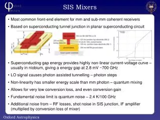
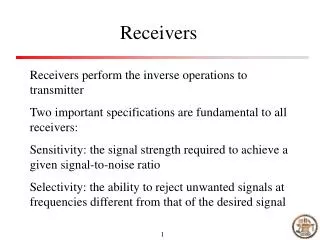
Overview • Mixers • Used for converting signals up or down in frequency. • A mixer is a circuit containing a nonlinear device. • Frequency conversion is accomplished by multiplying. • The nonlinear device in the mixer performs the multiplication.
Receiver System Antenna fRF Mixer To Demodulator RF Filter/ Amplifier IF Filter/ Amplifier Local Oscillator fLO
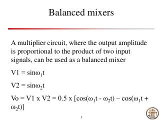
Multiplication of Cosines • Recall the following trigonometric identity: • Take a multiplier and input two sinusoids of different frequencies:
A More Realistic Mixer • Sum the RF and LO signals, then input them into a diode. • Diode Current-Voltage Characteristic: I(V) RF Input Combiner LO Input V
A More Realistic Mixer • Mixer Input: • Mixer Output: DC Difference RF LO 2nd Harmonic of RF Sum 2nd Harmonic of LO
“Squarelaw” Mixer Output Spectrum Spectrum (Power or voltage) fIF f fRF fLO 2fRF fRF+fLO 2fLO
A Microwave Diode Mixer λ/4 Harmonic Tuning Stub RF Input 50 Ω λ/4 λ/4 near fRF, fLO Diode LO Input IF Output RF Choke Inductor λ/4 DC return path