Download
1 / 44
771 likes | 1.61k Vues
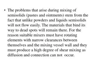
Emad Hegazi Professor, ECE Communication Circuits Research Group http://portal.eng.asu.edu.eg/emadhegazi/. Mixers. RF Systems and Circuits. Spring 2014. Mixer Design. Introduction to mixers Mixer metrics Mixer topologies Mixer performance analysis Mixer design issues.

E N D
EmadHegazi Professor, ECE Communication Circuits Research Group http://portal.eng.asu.edu.eg/emadhegazi/ Mixers RF Systems and Circuits Spring 2014
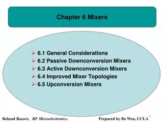
Mixer Design • Introduction to mixers • Mixer metrics • Mixer topologies • Mixer performance analysis • Mixer design issues RF Systems and Circuits Spring 2014
What is a mixer • Frequency translation device • Convert RF frequency to a lower IF or base band for easy signal processing in receivers • Convert base band signal or IF frequency to a higher IF or RF frequency for efficient transmission in transmitters • Creative use of nonlinearity or time-variance • These are usually harmful and unwanted • They generates frequencies not present at input • Used together with appropriate filtering • Remove unwanted frequencies RF Systems and Circuits Spring 2014
Two operation mechanisms • Nonlinear transfer function • Use device nonlinearities creatively! • Intermodulation creates the desired frequency and unwanted frequencies • Switching or sampling • A time-varying process • Preferred; fewer spurs • Active mixers • Passive mixers RF Systems and Circuits Spring 2014
The Ideal Mixer If x(t)y(t) x(t) RF Systems and Circuits y(t) Then the output is down convert up convert Spring 2014
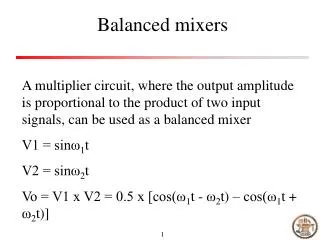
Is the mixer really a multiplier? • Not really, in fact, it should not. Why? RF Systems and Circuits Spring 2014
Commutating switch mixer RF Systems and Circuits Spring 2014
A non-ideal mixer RF Systems and Circuits Spring 2014
Mixer Metrics • Conversion gain – lowers noise impact of following stages • Noise Figure – impacts receiver sensitivity • Port isolation – want to minimize interaction between the RF, IF, and LO ports • Linearity (IIP3) – impacts receiver blocking performance • Spurious response • Power match – want max voltage gain rather than power match for integrated designs • Power – want low power dissipation • Sensitivity to process/temp variations – need to make it manufacturable in high volume RF Systems and Circuits Spring 2014
Conversion Gain • Conversion gain or loss is the ratio of the desired IF output (voltage or power) to the RF input signal value ( voltage or power). RF Systems and Circuits Spring 2014 If the input impedance and the load impedance of the mixer are both equal to the source impedance, then the voltage conversion gain and the power conversion gain of the mixer will be the same in dB’s.
Noise Figures: SSB vs DSB RF Systems and Circuits Signal band Signal band Image band Thermal noise Thermal noise LO LO Spring 2014 0 IF Single side band Double side band
SSB Noise Figure • Broadband noise from mixer or front end filter will be located in both image and desired bands • Noise from both image and desired bands will combine in desired channel at IF output • Channel filter cannot remove this RF Systems and Circuits Spring 2014
DSB Noise Figure • For zero IF, there is no image band • Noise from positive and negative frequencies combine, but the signals combine as well • DSB noise figure is 3 dB lower than SSB noise figure • DSB noise figure often quoted since it sounds better RF Systems and Circuits Spring 2014
Port-to-Port Isolations • Isolation • Isolation between RF, LO and IF ports • LO/RF and LO/IF isolations are the most important features. • Reducing LO leakage to other ports can be solved by filtering. RF Systems and Circuits IF RF Spring 2014 LO
LO Feed through • Feed through from the LO port to IF output port due to parasitic capacitance, power supply coupling, etc. • Often significant due to strong LO output signal • If large, can potentially desensitize the receiver due to the extra dynamic range consumed at the IF output • If small, can generally be removed by filter at IF output RF Systems and Circuits Spring 2014
Reverse LO Feed through • Reverse feed through from the LO port to RF input port due to parasitic capacitance, etc. • If large, and LNA doesn’t provide adequate isolation, then LO energy can leak out of antenna and violate emission standards for radio • Must insure that isolation to antenna is adequate RF Systems and Circuits Spring 2014
Self-Mixing of Reverse LO Feedthrough • LO component in the RF input can pass back through the mixer and be modulated by the LO signal • DC and 2fo component created at IF output • Of no consequence for a heterodyne system, but can cause problems for homodyne systems (i.e., zero IF) RF Systems and Circuits Spring 2014
Nonlinearity in Mixers • Ignoring dynamic effects, three nonlinearities around an ideal mixer • Nonlinearity A: same impact as LNA nonlinearity • Nonlinearity B: change the spectrum of LO signal • Cause additional mixing that must be analyzed • Change conversion gain somewhat • Nonlinearity C: cause self mixing of IF output RF Systems and Circuits Spring 2014
Focus on Nonlinearity in RF Input Path • Nonlinearity B not detrimental in most cases • LO signal often a square wave anyway • Nonlinearity C avoidable with linear loads • Nonlinearity A can hamper rejection of interferers • Characterize with IIP3 as with LNA designs • Use two-tone test to measure (similar to LNA) RF Systems and Circuits Spring 2014
Mixer topologies • Discrete implementations: • Single-diode and diode-ring mixers • IC implementations: • MOSFET passive mixer • Active mixers • Gilbert-cell based mixer • Square law mixer • Sub-sampling mixer • Harmonic mixer RF Systems and Circuits Spring 2014
Single-diode passive mixer • Simplest and oldest passive mixer • The output RLC tank tuned to match IF • Input = sum of RF, LO and DC bias • No port isolation and no conversion gain. • Extremely useful at very high frequency (millimeter wave band) RF Systems and Circuits Spring 2014
Single-balanced diode mixer RF Systems and Circuits • Poor gain • Good LO-IF isolation • Good LO-RF isolation • Poor RF-IF isolation • Attractive for very high frequency applications where transistors are slow. Spring 2014
Double-balanced diode mixer RF Systems and Circuits • Poor gain (typically -6dB) • Good LO-IF LO-RF RF-IF isolation • Good linearity and dynamic range • Attractive for very high frequency applications where transistors are slow. Spring 2014
CMOS Passive Mixer • Use switches to perform the mixing operation • No bias current required • Allows low power operation to be achieved RF Systems and Circuits Spring 2014
CMOS Passive Mixer • Non-50% duty cycle of LO results in no DC offsets!! DC-term of LO RF Systems and Circuits Spring 2014
A Highly Linear CMOS Mixer • Transistors are alternated between the off and triode regions by the LO signal • RF signal varies resistance of channel when in triode • Large bias required on RF inputs to achieve triode operation • High linearity achieved, but very poor noise figure RF Systems and Circuits Spring 2014
Simple Switching Mixer (Single Balanced Mixer) • The transistor M1 converts the RF voltage signal to the current signal. • Transistors M2 and M3 commute the current between the two branches. RF Systems and Circuits Spring 2014
MOS Single Balanced Mixer • The transistor M1 converts the RF voltage signal to the current signal. • Transistors M2 and M3 commute the current between the two branches. RF Systems and Circuits Spring 2014
MOS Single Balanced Mixer RF Systems and Circuits Spring 2014
MOS Single Balanced Mixer RF Systems and Circuits IF Filter Spring 2014
w - w w + w w - w LO RF LO RF LO RF MOS Single Balanced Mixer IF Filter
w RF w S LO LO w - w LO RF MOS Single Balanced Mixer RF Systems and Circuits Spring 2014
Single Balanced Mixer Analysis: Linearity • Linearity of the Mixer primarily depends on the linearity of the transducer (I_tail=Gm*V_rf). Inductor Ls helps improve linearity of the transducer. • The transducer transistor M1 can be biased in the linear law region to improve the linearity of the Mixer. Unfortunately this results in increasing the noise figure of the mixer (as discussed in LNA design).
Single Balanced Mixer Analysis: Linearity RF Systems and Circuits Spring 2014 • Using the common gate stage as the transducer improves the linearity of the mixer. Unfortunately the approach reduces the gain and increases the noise figure of the mixer.
Single Balanced Mixer Analysis: Isolation LO-RF Feed through • The strong LO easily feeds through and ends up at the RF port in the above architecture especially if the LO does not have a 50% duty cycle. Why?
Single Balanced Mixer Analysis: Isolation Weak LO-RF Feed through • The amplified RF signal from the transducer is passed to the commuting switches through use of a common gate stage ensuring that the mixer operation is unaffected. Adding the common gate stage suppresses the LO-RF feed through.
Single Balanced Mixer Analysis: Isolation LO-IF Feed through RF Systems and Circuits Spring 2014 • The strong LO-IF feed-through may cause the mixer or the amplifier following the mixer to saturate. It is therefore important to minimize the LO-IF feed-through.
Double Balanced Mixer RF Systems and Circuits Spring 2014 • Strong LO-IF feed suppressed by double balanced mixer. • All the even harmonics cancelled. • All the odd harmonics doubled (including the signal).
Double Balanced Mixer • The LO feed through cancels. • The output voltage due to RF signal doubles.
Gilbert Mixer • Use a differential pair to achieve the transconductor implementation • This is the preferred mixer implementation for most radio systems! RF Systems and Circuits Spring 2014
Mixers based on MOS square law RF Systems and Circuits Spring 2014
Practical Square Law Mixers RF Systems and Circuits Spring 2014
Features of CMOS Square Law Mixers • Noise Figure: very low. • Linearity: produces only DC, original tones, difference, and sum tones • The corresponding BJT mixer produces a lot of non-linear components due to the exponential function • Power Dissipation: The square law mixer can be designed with very low power dissipation. • Power Gain: Reasonable power gain can be achieved. • Isolation: poor isolation from LO to RF port. This is by far the biggest short coming of the square law mixers. RF Systems and Circuits Spring 2014
Sub-sampling Mixer • Properly designed track-and-hold circuit works as sub-sampling mixer. • The sampling clock’s jitter must be very small • Noise folding leads to large mixer noise figure. • High linearity RF Systems and Circuits Spring 2014