Download
1 / 60
600 likes | 702 Vues
Project: IEEE P802.15 Working Group for Wireless Personal Area Networks (WPANs) Submission Title: [ TI Physical Layer Proposal ] Date Submitted: [ 05 May, 2003 ] Source: [ Anuj Batra, Jaiganesh Balakrishnan, Anand Dabak, et al. ] Company [ Texas Instruments ]

E N D
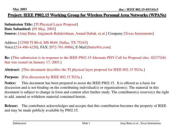
Project: IEEE P802.15 Working Group for Wireless Personal Area Networks (WPANs) Submission Title: [TI Physical Layer Proposal] Date Submitted: [05 May, 2003] Source: [Anuj Batra, Jaiganesh Balakrishnan, Anand Dabak, et al.] Company [Texas Instruments] Address [12500 TI Blvd, MS 8649, Dallas, TX 75243] Voice:[214-480-4220], FAX: [972-761-6966], E-Mail:[batra@ti.com] Re: [This submission is in response to the IEEE P802.15 Alternate PHY Call for Proposal (doc. 02/372r8) that was issued on January 17, 2003.] Abstract: [This document describes the TI physical layer proposal for IEEE 802.15 TG3a.] Purpose: [For discussion by IEEE 802.15 TG3a.] Notice: This document has been prepared to assist the IEEE P802.15. It is offered as a basis for discussion and is not binding on the contributing individual(s) or organization(s). The material in this document is subject to change in form and content after further study. The contributor(s) reserve(s) the right to add, amend or withdraw material contained herein. Release: The contributor acknowledges and accepts that this contribution becomes the property of IEEE and may be made publicly available by P802.15. Anuj Batra et al., Texas Instruments
TI Physical Layer Proposal:Time-Frequency Interleaved OFDM Anuj Batra, Jaiganesh Balakrishnan, Anand Dabak Ranjit Gharpurey, Paul Fontaine, Jerry Lin Jin-Meng Ho, Simon Lee, Michel Frechette Steven March, Hirohisa Yamaguchi Texas Instruments12500 TI Blvd, MS 8649Dallas, TXMay 5, 2003 Anuj Batra et al., Texas Instruments
Outline • Overview of OFDM: History, strengths, worldwide compliance. • Optimal operating bandwidth. • Details about Time-Frequency Interleaved OFDM (TFI-OFDM). • Performance Results: • Link budget. • System performance in multi-path. • Simultaneously operating piconets and robustness to coexistence. • Complexity. • Summary and Conclusions. Anuj Batra et al., Texas Instruments
History of OFDM • OFDM was invented more than 40 years ago. • OFDM has been adopted by several standards: • Asymmetric Digital Subscriber Line (ADSL) services. • IEEE 802.11a/g. • IEEE 802.16a. • Digital Audio Broadcast (DAB). • Digital Terrestrial Television Broadcast: • DVB in Europe and ISDB in Japan. • Because OFDM is suitable for high data-rate systems, it is being considered for the following standards: • Fourth generation (4G) wireless services. • IEEE 802.11n, IEEE 802.16, and IEEE 802.20. Anuj Batra et al., Texas Instruments
Strengths of OFDM (1) • OFDM is spectrally efficient: • IFFT/FFT operation ensures that sub-carriers do not interfere with one other. • Since the sub-carriers do not interfere, the sub-carrier can be brought closer together High spectral efficiency. • OFDM has an inherent robustness against narrowband interference: • Narrowband interference will affect at most a couple of tones. • Do not have to drop the entire band because of narrowband interference. • Erase information from the affected tones, since they are now unreliable. Use FECs to recover the lost information. Anuj Batra et al., Texas Instruments
Strengths of OFDM (2) • OFDM has excellent robustness in multi-path environments. • Cyclic prefix preserves orthogonality between sub-carriers. Anuj Batra et al., Texas Instruments
Strengths of OFDM (3) • OFDM has excellent robustness in multi-path environments: • Allows receiver to capture multi-path energy more efficiently. Anuj Batra et al., Texas Instruments
Worldwide Compliance (1) • Example: Ministry of Public Management, Home Affairs, Posts, and Telecommunications in Japan has set aside seven bands for radio-astronomy. • 3260.0 – 3267.0 MHz (used for line spectral measurement) • 3332.0 – 3339.0 MHz (same as above) • 3345.8 – 3352.5 MHz (same as above) • 4825.0 – 4835.0 MHz (same as above) • 4950.0 – 4990.0 MHz • 4990.0 – 5000.0 MHz • 6650.0 – 6675.2 MHz • The Ministry has taken measures to ensure that these services will be free of interference. • With OFDM, these services can be protected by turning off the tones near these particular frequencies. Anuj Batra et al., Texas Instruments
Worldwide Compliance (2) • Example: consider a TFI-OFDM systems, which uses 3 channels. • Channel #1: 3168 – 3696 MHz. • Channel #2: 3696 – 4224 MHz. • Channel #3: 4224 – 4752 MHz. • Only need to protect the first 3 radio astronomy bands. No modifications are required in order to protect the other 4 bands. • Solution: Zero out tones near these frequencies to protect these 3 bands. Anuj Batra et al., Texas Instruments
Optimal Operating Bandwidth (1) • Only incremental gains (less than 1 dB) can be realized by using frequencies above 4.8 GHz. • Start with the frequency band from 3.1 to 4.8 GHz: • Simplifies the front-end design: LNA and mixers (CMOS friendly). • Avoids the U-NII band entirely. Quicker time to market! • As the RF technology improves, can start using the higher band in addition to the lower band. • Using the upper band (adding more channels) will increase the multiple piconet performance Anuj Batra et al., Texas Instruments
Optimal Operating Bandwidth (2) • Another reason for avoiding frequencies higher than 4.8 GHz is to simplify the design of off-chip filters. • Avoid the U-NII band entirely. • Pre-select filter only needs to span the frequencies: 3.1 – 4.8 GHz. • Block diagram of standard pre-select filter: • Pre-select serves 4 purposes: • Selects the desired band. • Limits out of band noise. • Suppresses out-of-band interference (U-NII and ISM). • Relaxes the filtering requirements for the remainder of the analog chain (ex. channel select filter). Anuj Batra et al., Texas Instruments
Optimal Operating Bandwidth (3) • If the operating BW includes the U-NII band, then interference mitigation strategies have to be included in the receiver design to prevent analog front-end saturation. • Example: Switchable filter architecture. • When no U-NII interference is present, use standard pre-select filter. • When U-NII interference is present, pass the receive signal through a different filter (notch filter) that suppresses the entire U-NII band. • Problems with this approach: • Extra switches more insertion loss in RX/TX chain. • More external components higher BOM cost. • More testing time. Anuj Batra et al., Texas Instruments
Design of a Notch Filter • Design of a “relatively” narrowband notch filter is a challenging problem: • Need greater than 30 dB of rejection (03/142) over the entire U-NII band to meet desired criteria. • Transition region is ~150 MHz on either side of the band. • Example filter design using ideal components (5th-order equal-ripple elliptic): • Problem: Frequencies between 5.05 – 5.95 GHz are no longer usable. • Problem: Significant group delay variations at the edge of the notch filter. • May be possible to design 3 individual notch filters that remove just the Lower, Middle U-NII bands, the Upper U-NII band, and the Japanese U-NII band. • Incorporating these off-chip filters into the design will require even more switches even more insertion loss in the RX/TX chains. Anuj Batra et al., Texas Instruments
Proposed System:Time Frequency Interleaved OFDM Anuj Batra et al., Texas Instruments
Time-Frequency Interleaved OFDM • Basic idea: divide spectrum (3.1 – 4.8 GHz) into 3 sub-bands, where each band is 528 MHz wide. • Information is transmitted using OFDM modulation on each band. • OFDM carriers are efficiently generated using an 128-point IFFT/FFT. • Internal precision is reduced by limiting constellation size to QPSK. • Information bits are interleaved across all the three bands (3 OFDM symbols) to exploit frequency diversity and provide robustness against multi-path and interference. • 60.6 ns cyclic prefix provides robustness against multi-path even in the worst channel environments. • 9.5 ns guard interval provides sufficient time for switching between bands. Anuj Batra et al., Texas Instruments
TFI-OFDM Physical Layer • Interleave OFDM symbols across sub-bands. • Transmitter and receiver process smaller bandwidth signals (528 MHz). • Insert a guard interval between OFDM symbols in order to allow sufficient time to switch between channels. • TFI-OFDM needs only a single TX/RX chain for all data rates and all channel environments. Anuj Batra et al., Texas Instruments
Details of the TFI-OFDM System *More details about the TFI-OFDM system can be found in the latest version of 03/142. Anuj Batra et al., Texas Instruments
TFI-OFDM: Example TX Architecture • Block diagram of an example TX architecture: • Architecture is similar to that of a conventional and proven OFDM system. Can leverage existing OFDM solutions for the development of the TFI-OFDM physical layer. • For a given superframe, the interleaving pattern is specified in the beacon by the PNC. The interleaving pattern is rotated across multiple superframes to mitigate multi-piconet interference. Anuj Batra et al., Texas Instruments
TFI-OFDM System Parameters • System parameters for rates specifically mentioned in selection criteria document: Anuj Batra et al., Texas Instruments
Simplified TX Analog Section • For rates up to 200 Mb/s, the input to the IFFT is forced to be conjugate symmetric (for spreading gains 2). • Output of the IFFT is REAL. • The analog section of TX can be simplified when the input is real: • Need to only implement the “I” portion of DAC and mixer. • Only requires half the analog die size of a complete “I/Q” transmitter. • For rates > 200 Mb/s, need to implement full “I/Q” transmitter. Anuj Batra et al., Texas Instruments
More Details on the OFDM Parameters • By using a contiguous set of orthogonal carriers, the transmit spectrum will always occupy a bandwidth greater than 500 MHz. • Total of 128 tones: • 100 data tones used to transmit information (constellation: QPSK). • 12 pilot tones used for carrier and phase tracking. • 10 user-defined pilot tones. • Remaining 6 tones including DC are NULL tones. • User-defined pilot tones: • Carry no useful information. • Energy is placed on these tones to ensure that the spectrum has a bandwidth greater than 500 MHz. • Can trade the amount of energy placed on tones for relaxing analog filtering specifications. • Ultimately, the amount of energy placed on these tones is left to the implementer. Provides a level of flexibility for the implementer. Anuj Batra et al., Texas Instruments
Potential Coding Schemes • Several different potential coding schemes: • Convolutional codes. • Block codes. • Concatenated codes – block codes plus convolutional codes. • Turbo codes. • There are trade-offs in selecting any of these codes. • The proposal uses convolutional codes, which provides the best trade-off in terms of performance and complexity for a target BER = 10-5. Anuj Batra et al., Texas Instruments
Bit Interleaver (1) • Bit interleaving is performed across the bits within an OFDM symbol and across at most three OFDM symbols. • Exploits frequency diversity. • Randomizes any interference interference looks nearly white. • Latency is less than 1 ms. • Bit interleaving is performed in three stages: • First, 3NCBPS coded bits are grouped together. • Second, the coded bits are interleaved using a NCBPS3 block symbolinterleaver. • Third, the output bits from 2nd stage are interleaved using a (NCBPS/10)10 block tone interleaver. • The end results is that the 3NCBPS coded bits are interleaved across 3 symbols and within each symbol. • If there are less than 3NCBPS coded bits, which can happen at the end of the header or near the end of a packet, then the second stage of the interleaving process is skipped. Anuj Batra et al., Texas Instruments
Bit Interleaver (2) • Ex: Second stage (symbol interleaver) for a data rate of 110 Mbps • Ex: Third stage (tone interleaver) for a data rate of 110 Mbps Anuj Batra et al., Texas Instruments
Channelization • The relationship between fc and channel number nch is • Initially, only the first 3 channels will be defined. • More channels can be added as RF technology improves. Anuj Batra et al., Texas Instruments
Frequency Synthesis (1) • All three frequencies can be generated rapidly using the single-sideband (SSB) generation principle: • Cos(w1t) Cos(w2t) – Sin(w1t) Sin(w2t) = Cos[(w1 + w2)t] • Cos(w1t) Sin(w2t) + Sin(w1t) Cos(w2t) = Sin[(w1 + w2)t] • Let the VCO center frequency = 4224 MHz • Divide by 4 1056 MHz and Divide by 16 264 MHz • Center frequencies for individual sub-bands: • Channel #1: 4224 – 1056 + 264 MHz = 3432 MHz. • Channel #2: 4224 – 264 MHz = 3960 MHz. • Channel #3: 4224 + 264 MHz = 4488 MHz. Anuj Batra et al., Texas Instruments
Frequency Synthesis (2) • Circuit-level simulation of frequency synthesis: • Nominal switching time = ~2 ns. • Need to use a slightly larger switching time to allow for process and temperature variations. Anuj Batra et al., Texas Instruments
TFI-OFDM: PLCP Frame Format • PLCP frame format: • Rates supported: 55, 80, 110, 160, 200, 320, 480 Mb/s. Support for 55, 110, and 200 Mb/s is mandatory. • Preamble length = 9.38 ms. Burst preamble length = 4.69 ms. • For the sake of robustness, the PLCP header, MAC header, HCS, and tail bits are always sent at the information data rate of 55 Mb/s. • PLCP header + MAC header + HCS + tail bits = 2.19 ms. • Maximum frame payload supported is 4095 bytes. Anuj Batra et al., Texas Instruments
PLCP Preamble (1) • Preamble is divided into 3 distinct and separate sections: • Packet synchronization sequence (21 symbols). • Frame synchronization sequence (3 symbols). • Channel estimation sequence (6 symbols). Anuj Batra et al., Texas Instruments
PLCP Preamble (2) • Packet synchronization sequence: • Time-domain sequence is a hierarchical sequence. • Correlators using these sequences can be implemented efficiently, i.e., with low power and low complexity. • Designed this portion of the preamble to be more robust than the header. • Frame synchronization sequence: • This sequence is 180º out of phase with the packet sync sequence. • Provides a clean and detectable boundary between the two sequences. • Channel estimation sequence: • Sequence is used for frequency-domain channel estimation. Anuj Batra et al., Texas Instruments
Link Budget and Receiver Sensitivity • Assumption: AWGN and 0 dBi gain at TX and RX antennas. Anuj Batra et al., Texas Instruments
System Performance • The distance at which the TFI-OFDM system can achieve a PER of 8% for a 90% link success probability is tabulated below**: * Includes losses due to front-end filtering, clipping at the DAC, ADC degradation, multi-path degradation, channel estimation, carrier tracking, packet acquisition, etc. All results incorporate shadowing. ** Results obtained using new channel model. Anuj Batra et al., Texas Instruments
Simultaneously Operating Piconets (1) • Bandwidth expansion refers to using a signaling bandwidth that is much larger than the information data rate. • Bandwidth expansion can be achieved using any of the following techniques or combination of techniques: • Spreading, Time-frequency interleaving, Coding • Ex: TFI-OFDM obtains its BW expansion by using all three techniques. Anuj Batra et al., Texas Instruments
Simultaneously Operating Piconets (2) • However, multi-path and asynchronicity between piconets ensures that spreading sequences and TF codes will never be truly orthogonal. • Can never have perfect isolation between piconets. • Multiple piconet performance is governed by SIR = (Psig/Pint) (W/R). Note that SIR is directly related to bandwidth expansion (W/R). • In realistic multi-path, real-world conditions: “BW expansion is all that matters”. • Systems with same BW expansion have similar multiple piconet capability. Anuj Batra et al., Texas Instruments
Simultaneously Operating Piconets (3) • Assumptions: • As specified in 03/031r9, dref= 10.0 meters for all tests. • Single piconet (N= 1) interferer separation distance as a function of the reference and interfering multipath channel environments: • Results for N = 2 and N = 3 interferers as well as FDMA can be found in 03/142r2. Interferer Link Test Link Anuj Batra et al., Texas Instruments
Signal Robustness/Coexistence • Assumption: received signal is 6 dB above sensitivity. • Value listed below are the required distance or power level needed to obtain a PER 8% for a 1024 byte packet. • Coexistence with 802.11a/b and Bluetooth is relatively straightforward because these bands are completely avoided. Anuj Batra et al., Texas Instruments
PHY-SAP Throughput • Assumptions: • MPDU (MAC frame body + FCS) length is 1024 bytes. • SIFS = 10 ms. • MIFS = 2 ms. • Assumptions: • MPDU (MAC frame body + FCS) length is 4024 bytes. Anuj Batra et al., Texas Instruments
Complexity (1) • Unit manufacturing cost (selected information): • Process: CMOS 90 nm technology node in 2005. • CMOS 90 nm production will be available from all major SC foundries by early 2004. • Die Size: • Power consumption (analog plus digital): * Component area. Anuj Batra et al., Texas Instruments
Complexity (2) • Manufacturability: • Leveraging standard CMOS technology results in a straightforward development effort. • OFDM solutions are mature and have been demonstrated in ADSL and 802.11a/g solutions. • Time to market: the earliest complete CMOS PHY solutions would be ready for integration is 2005. • Size: Solutions for PC card, compact flash, memory stick, SD memory in 2005. Anuj Batra et al., Texas Instruments
FFT/IFFT Complexity • Number of complex multipliers and complex adders needed per clock cycle for a 128 point FFT. • OFDM efficiently captures multi-path energy with lower complexity! • 128-point FFT is realizable in current CMOS technology. • A technical contribution (03/213) by Roger Bertschmann (SiWorks, Inc.) shows that they have a 128-point IFFT/FFT core which can be used in a TFI-OFDM system. • The synthesized core has a gate count of approximately 70K gates in a 130 nm TSMC process. Anuj Batra et al., Texas Instruments
Comparison of OFDM Technologies • Qualitative comparison between TFI-OFDM and IEEE 802.11a OFDM: 1. Assumes a 256-point FFT for IEEE 802.11a. 2. Assumes a 128-point FFT for IEEE 802.11a. Anuj Batra et al., Texas Instruments
TFI-OFDMAdvantages (1) • Suitable for CMOS implementation (all components). • Only one transmit and one receive chain at all times, even in the presence of multi-path. • Antenna and pre-select filter are easier to design (can possibly use off-the-shelf components). • Early time to market! • Low cost, low power, and CMOS integrated solution leads to: • Early market adoption! Anuj Batra et al., Texas Instruments
TFI-OFDMAdvantages (2) • Inherent robustness in all the expected multipath environments. • Excellent robustness to ISM, U-NII, and other generic narrowband interference. • Ability to comply with world-wide regulations: • Channels and tones can be dynamically turned on/off to comply with changing regulations. • Coexistence with current and future systems: • Channels and tones can be dynamically turned on/off for enhanced coexistence with the other devices. • Scalability: • More channels can be added as the RF technology improves. • Digital section complexity/power scales with improvements in technology nodes (Moore’s Law). • Analog section complexity/power scales poorly with technology node. Anuj Batra et al., Texas Instruments
Summary • The proposed system is specifically designed to be a low power, low complexity all CMOS solution. • Expected range for 110 Mb/s: 20.5 meters in AWGN, and greater than 11 meters in multipath environments. • Expected power consumption for 110 Mb/s: • 90 nm process: 93 mW (TX), 155 mW (RX), 15 mW (deep sleep). • 130 nm process: 117 mW (TX), 205 mW (RX), 18 mW (deep sleep). • TFI-OFDM is coexistence friendly and complies with world-wide regulations. • PHY solution are expected to be ready for integration in 2005. • TFI-OFDM offers the best trade-off between the various system parameters. Anuj Batra et al., Texas Instruments
Backup slides Anuj Batra et al., Texas Instruments
Self-evaluation Matrix (1) Anuj Batra et al., Texas Instruments
Self-evaluation Matrix (2) Anuj Batra et al., Texas Instruments
Convolutional Encoder • Assume a mother convolutional code of R = 1/3, K = 7. Having a single mother code simplifies the implementation. • Generator polynomial: g0 = [1338], g1 = [1458], g2 = [1758]. • Higher rate codes are achieved by puncturing the mother code. Puncturing patterns are specified in latest revision of 03/142. Anuj Batra et al., Texas Instruments
TFI-OFDM: Example RX Architecture • Block diagram of an example RX architecture: • Architecture is similar to that of a conventional and proven OFDM system. Can leverage existing OFDM solutions for the development of the TFI-OFDM physical layer. Anuj Batra et al., Texas Instruments
Simulation Parameters • Assumptions: • System as defined in 03/142. • Clipping at the DAC (PAR = 9 dB). • Finite precision ADC (4 bits @ 110/200 Mbps). • Degradations incorporated: • Front-end filtering. • Multi-path degradation. • Clipping at the DAC. • Finite precision ADC. • Crystal frequency mismatch (20 ppm @ TX, 20 ppm @ RX). • Channel estimation. • Carrier offset recovery. • Carrier tracking. • Packet acquisition. Anuj Batra et al., Texas Instruments