Download
1 / 22
230 likes | 463 Vues
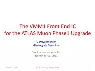
Front-End ASIC for the ATLAS New Small Wheels. Gianluigi De Geronimo , Alessio D'Andragora, Jack Fried, Neena Nambiar, Emerson Vernon, and Venetios Polychronakos Brookhaven National Laboratory ACES 2014 - CERN March 2014. ASIC for ATLAS Muon Spectrometer Upgrade.

E N D
Front-End ASIC for the ATLAS New Small Wheels Gianluigi De Geronimo, Alessio D'Andragora, Jack Fried, Neena Nambiar, Emerson Vernon, and Venetios Polychronakos Brookhaven National Laboratory ACES 2014 - CERN March 2014
ASIC for ATLAS Muon Spectrometer Upgrade • Front-end Electronics (ASIC) • more than 2.3 million channels total • operate with both charge polarities • sensing element capacitance 10-200 pF • charge meas. up to 2 pC @ < 1 fC rms • time meas. ~ 100 ns @ < 1 ns rms • trigger primitives, neighbor logic • low power, programmable • New Small Wheels • sTGC • Small Strip Thin Gap Chamber • MM • MicroMegas • (MICROMEsh GAseous Structure)
VMM Front-end ASIC VMM is a 64-channel front-end ASIC for the read out the sTGCand MM sensors in the New Small Wheels version 2 version 1 VMM2, year 2014 size 13.5 × 8.4 mm² > 5M transistors (> 80k/ch.) a considerable step-up in complexity - being fabricated - VMM1, year 2012 size 5.9 × 8.4 mm² 500k transistors (8k/ch.) a complex mixed-signal ASIC - extensively tested -
VMM2 Architecture - Analog Front-End CA shaper test • input transistor: PMOS 180 nm x 20 mm, 2 mA • input capacitance: optimized for 200 pF, can operate from sub-pF to nF • polarity: adjustable positive or negative • gain: adjustable 0.5, 1, 3, 4.5, 6, 9, 12, 16 mV/fC (max charge 2 to 0.06 pC) • peaking time: adjustable 25, 50, 100, 200 ns • leakage-adaptive, DDF shaper, BGR-stabilized baseline, test capacitor, mask
VMM2 Architecture - Discriminator, Neighbor Logic neighbor logic CA shaper test trim • adjustable discrimination threshold per channel • trimming range: 15 mV in 1m increments • comparator hysteresis: ~ 20 mV • sub-hysteresis discrimination: effective discrimination ~ 2 mV • neighbor logic: processing of sub-threshold neighbor channels • inter-chip communication: neighbor channel logic includes neighbor chips
VMM2 Architecture - Direct Timing Measurements neighbor TGC out (ToT, TtP, PtT, PtP) logic CA shaper test trim • direct digital output per channel: LVDS 600 mV +/- 150 mV • selectable measurements: - time-over-threshold (ToT) • - threshold-to-peak (TtP) • - peak-to-threshold (PtP) • - pulse at peak (PtP) • continuous self-reset operation
VMM2 Architecture - Peak and Time Detectors neighbor TGC out (ToT, TtP, PtT, PtP, 6bADC) logic CA shaper peak time test trim • peak detection: measurement of peak amplitude and storage in analog memory • time detection: measurement of peak time and storage in analog memory • sub-mV resolution on amplitude measurement • sub-ns resolution, low time-walk on peak time measurement • multi-phase offset-free measurement circuits • adjustable time-to-amplitude converter (TAC): 125, 250, 500, 1000 ns • optional current output for current-mode ADCs
Resolution Measurements (VMM1) charge resolution timing resolution • ENC τP • Q • σt • ≈ • charge resolution ENC < 5,000 e- at 25 ns, 200 pF • analog dynamic range Qmax/ ENC > 12,000 → DDF • ≈ 0.3-0.8 • λP • timing resolution <1 ns • (at peak-detect) G. De Geronimo, in “Medical Imaging” by Iniewski • ρP
VMM2 Architecture - 6-bit ADC neighbor TGC out (ToT, TtP, PtT, PtP, 6bADC) logic TGC clock 6-b ADC CA shaper peak time test trim • lower-resolution ADC: - 6-bit, sub-mW, adjustable conversion time and offset • - clock-less single-stage current-mode domino architecture • - at threshold-crossing, completes in 25 ns from peaktime • at direct output: flag at peak followed by serialized address • clock frequency: up to 200 MHz • selectable serialized mode: either at each clock cycle or at each clock edge • continuous self-reset operation
Direct Output with 6-bit ADC 50ns 100ns 150ns 200ns 25ns 75ns 125ns 175ns analog pulse end of conversion end of encoding charge event reset end (ready for next event) peak-found CK OUT timing edge D5 - D0 • conversion completes within ~25 ns from peak • dead time from charge event < 100 ns • 6-bit amplitude D5-D0 shifted at each clock cycle or edge • up to 200 MHz readout
VMM2 Architecture - 10-bit and 8-bit ADCs neighbor mixed-signal channel (x 64) 80,000 MOSFETs ~ 4-8mW TGC out (ToT, TtP, PtT, PtP, 6bADC) logic TGC clock 6-b ADC CA shaper peak 10-b ADC 8-b ADC time test trim • higher-resolution ADCs: - 10-bit , 200 ns , sub-mW, for peak amplitude conversion • - 8-bit , 100 ns , sub-mW for timing conversion • - adjustable conversion time and offset • - clock-less dual-stage current-mode domino architecture • continuous self-reset operation
VMM2 Architecture - Timestamp and FIFO neighbor TGC out (ToT, TtP, PtT, PtP, 6bADC) logic TGC clock 6-b ADC CA shaper peak 10-b ADC 4X FIFO 8-b ADC time test 12-b BC addr. trim Gray count BC clock • 12-bit timestamp: - from shared 12-bit Gray-code counter, external BC clock • - stops TAC and latches coarse timing • complete timing information: 20-bit, ~100 µs with sub-ns resolution • 4-deep FIFO: threshold-crossing indicator, 10-bit ADC, 8-bit ADC, 12-bit BC • address memory
VMM2 Architecture - Complete Channel neighbor 64 channels TGC out (ToT, TtP, PtT, PtP, 6bADC) logic TGC clock 6-b ADC CA shaper peak 10-b ADC 4X FIFO 8-b ADC time test 12-b BC addr. trim Gray count BC clock • 64 independent channels • neighbor communication • 4-8 mW / channel depending on configuration layout size: 12 mm x 100 µm = 1 mm² 80,000 MOSFETs
VMM2 Architecture - Multiplexing and Readout neighbor 64 channels TGC out (ToT, TtP, PtT, PtP, 6bADC) logic data/TGC clock 6-b ADC flg 1-bit CA shaper peak thr 1-bit 10-b ADC data1 addr 6-bit 4X FIFO data2 mux 8-b ADC analog1 ampl 10-bit time analog2 test time 8-bit 12-b BC BC 12-bit addr. trim tk clock Gray count logic reset BC clock • sparse readout of amplitude/timing with token passing • readout options: • mixed-signal 2-phase: peak and time at analog outputs analog1,2 • address serialized at digital output data1 • fully digital continuous: 38-bit event data at digital outputs data1,2 • data1 also serves as empty flag • data shift at each clock cycle or at each clock edge • up to 200 MHz
VMM2 Architecture - Address in Real Time (ART) neighbor ART clock or ART (flag + serial address) 64 channels TGC out (ToT, TtP, PtT, PtP, 6bADC) logic data/TGC clock 6-b ADC flg 1-bit peak CA shaper thr 1-bit 10-b ADC data1 addr 6-bit 4X FIFO data2 mux 8-b ADC time analog1 ampl 10-bit analog2 test time 8-bit 12-b BC BC 12-bit addr. trim tk clock Gray count logic reset BC clock • address of first event (ART): - available at dedicated output ART • - first event flag followed by serialized event address • - shifted at each clock cycle or at each clock edge • - up to 200 MHz, self-reset
ART (Address in Real Time) 50ns 100ns 150ns 200ns 25ns 75ns 125ns 175ns analog pulse reset charge event peak-found CK ART FL D5 - D0 • flag and address serialized • 6-bit address D5-D0 shifted at each clock cycle or edge • up to 200 MHz readout
VMM2 Architecture - Additional Functions neighbor ART clock or ART (flag + serial address) 64 channels TGC out (ToT, TtP, PtT, PtP, 6bADC) logic data/TGC clock 6-b ADC flg 1-bit CA shaper peak thr 1-bit 10-b ADC data1 addr 6-bit 4X FIFO data2 mux 8-b ADC analog1 ampl 10-bit time analog2 test time 8-bit 12-b BC analog mon. BC 12-bit addr. trim tk clock Gray count bias pulser registers DAC temp logic reset BC clock tp clock prompt • coarse time counter: 12-bit Gray-code • test pulse generator: 10-bit adjustable • coarse threshold generator: 10-bit adjustable • analog monitor: analog signal, trimmed threshold, DACs, temperature • temperature sensor: ~ 725 mV - 1.85 mV/°C • configuration registers: 80-bit + 24-bit / channel • PROMPT (courtesy of CERN): export regulations (ITAR) compliance circuit
VMM2 Architecture - Complete ASIC neighbor ART clock or ART (flag + serial address) 64 channels TGC out (ToT, TtP, PtT, PtP, 6bADC) logic data/TGC clock 6-b ADC flg 1-bit CA shaper peak thr 1-bit 10-b ADC data1 addr 6-bit 4X FIFO data2 mux 8-b ADC analog1 ampl 10-bit time analog2 test time 8-bit 12-b BC analog mon. BC 12-bit addr. trim tk clock Gray count bias pulser DAC temp registers logic reset BC clock tp clock prompt • technology: IBM CMOS 130nm • power dissipation: 4-8+ mV/ch. • transistor count: > 5 million • coarse time counter: 12-bit Gray-code • test pulse generator: 10-bit adjustable • coarse threshold generator: 10-bit adjustable • temperature sensor: ~ 725 mV - 1.85 mV/°C • configuration registers: 80-bit + 24-bit / channel • PROMPT (courtesy of CERN): export regulations (ITAR) compliance circuit
Layout analog, mixed-signal, digital supplies (1.2V) – neigh.t – digital IOs (14) - TGC outs 0-6 64 inputs, 9 preamplifier supply (1.2V) TGC outs 7-42 analog, mixed-signal, digital supplies (1.8V) – neigh.b – TGC outs 43-63 • 1.5 mm • 300 µm • 70 µm • 15 µm • 5 µm • 13.5 mm all by hand (no automation) 392 bonding pads
A Few Notes • VMM2 is an extremely complex and ambitious ASIC • - a planned redesign of VMM1 to bring us closer to the final VMM - • Main risks from design complexity and layout parasitics • resolution may be affected by mixed-signal cross-talk • locking conditions may occur from complex control logic • 200 MHz operation may be affected by parasitics • performance(INL, DNL, ..) of novel ADCs to be verified • - extensive simulations done to mitigate these risks - • To be included in VMM3 • simultaneous direct- and multiplexed-operation • DSP for Level 1 handling and additional shared FIFO • test patterns and clock output • SEU mitigation circuits • any fixes on VMM2
Packaging custom BGA package 21 x 21 mm², 400-pin, 1 mm pitch
Schedule Acknowledgment NachmanLupu (Technion Haifa, Israel) -Lorne Levinson(Weizmann Inst., Israel) Ken Johns , Bill Hart(Univ. Arizona, USA) - GeorgeIakovidis(NTU Athens, Grece) SorinMartoiu(IFIN-HH Bucharest, Romania) - Jay Chapman(Michigan Univ., USA) AlessandroMarchioro(CERN) - Jessica Metcalfe(BNL, USA) - John Oliver(Harvard, USA) Veljko Radeka (BNL, USA), CERN, ATLAS Collaboration