Download
1 / 17
170 likes | 295 Vues
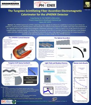
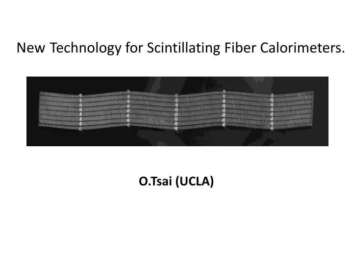
New Technology for Scintillating Fiber Calorimeters. O.Tsai (UCLA). Motivation: Develop simple, cost effective, flexible technique to build compact sampling calorimeters with good characteristics .

E N D
NewTechnology for Scintillating Fiber Calorimeters. O.Tsai (UCLA)
Motivation: Develop simple, cost effective, flexible technique to build compact sampling calorimeters with good characteristics. Simple – to the level that a typical university group can build it without heavy investments in “infrastructure”. Cost effective – fraction of the cost of crystals. Flexible – tunable for particular experiment requirements. Idea: Mix tungsten powder and scintillating fibers. Why this particular type?
Simple classification of different sampling calorimeters. I will classify sampling calorimeters in three different groups using this equation. First group has small d and Fs, second has small d but large Fs, and third has large d and Fs. Of course, boundaries are not well defined and there is migration between groups, but in general I think it will work for this discussion. [8] R.Wigmans, Calorimetry, Energy Measurement in Particle Physics. International Series of Monographs on Physics, Vol 107, Oxford University Press.
R.Wigmans , Calor 2010 Fiber calorimeters have a very good record. SPACAL still holds the record for best hadronic resolution. DREAM aims to set new standards in high resolution calorimetry.
We are proposing to develop new technology for (A) but keep the price tag from (C).
What else is so good in ScFi calorimeters that we wanted to develop new technology for this particular type? A bit of propaganda... Can a single detector do it all ?
Small Fs and small d domain. Let’s increase Sampling Frequency to reduce sampling fluctuations for a fixed Sampling Fraction Taken from CERN Yellow report, CERN-95-02 Better Resolution For fiber calorimeters for equal sampling fraction better resolution for smaller fiber diameter. But no one is building large detectors with fibers smaller than 0.5 mm. New technique required to build ScFi calorimeters with extremely high sampling frequency.
Why do we want to keep Fs small? (Besides compensation) Because we want the detector to be compact, with readout inside the magnet. Readout this- with something like that?
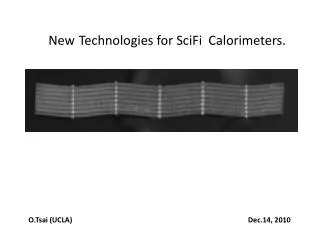
We did a little R&D back in 2003 /2004 in this direction. UCLA Mechanical Prototype 0.25x0.25, 0.3 mm fibers, 0.8 mm spacing H1, 0.5 mm fibers 0.8mm spacing.
We started with very simple “dry” version 4X4 matrix readout by APDs and mesh PMTs We tested it with the beam at SLAC in 2003, and found that it is too simple… That forced us to think a bit more and change technique to “wet”. The second version “spacardeon” has not been tested with the beam for a lot of different reasons… The idea is still need to be proven!
Test Beam Results from SLAC FFTB Goal was to measure resolution, linearity and uniformity Energy resolution for this configuration was modest: 30%/sqrt(E) Biggest problem was uniformity: Factor of 2 drop at corners of modules! Used most beam time to investigate this problem.
Uniformity Problem in Test Beam Results • Dry prototype was very dense, almost like • pure lead (10.3 g/cm3). It has 496 square • 0.25mm x 0.25mm fibers inside inside the • brass container with walls 62 mm thick. • 496 instead of 500 and 125 mm brass in • the corners explains largest variations in • response during transverse scans • (factor of two). • Compactness requires very strict • tolerances and homogeneity inside • the towers to keep response uniform. • 2. Dead materials and areas need • to be eliminated. Electromagnetic showers are really very narrow!
Second Prototype • Add additional meshes to keep fibers in place along the towers. • Learned how to infuse epoxy into powder/fiber mixture. • Remove container • Additional meshes allow us to wiggle the fibers. Learned by building a few mechanical units which we cut open to see how uniform they are: 2% for 2 cm thickness 2 cm is also the depth we can infuse epoxy without pressure: pull vacuum and let epoxy flow into the assembly Believe we have addressed all mechanical issues with first prototype.
Wiggle or not is a question. However for some applications where channeling is an issue this will help. Plus: Increased sampling frequency for given number of fibers. More fibers will contribute to a signal, thus fiber-to-fiber variations will be diminished. Minus: It is reasonably easy to wiggle 340 fibers of 0.3 mm diameter, but more than that will be a problem . From M.Livan “The art of Calorimetry, Lecture iV”
Plans for 2010: Instrument Second Prototype with MPPC (Multi-Pixel Photon Counters) Install inside STAR Forward Meson Spectrometer Take Data during 2011 Run Plans for 2011: Build 6x6 Matrix Test at FNAL or CERN Tower Size: 2 cm x 2 cm or 2.8 cm x 2.8 cm 20 Radiation Lengths Radiation Length: X0 = 0.7 cm Moliere Radius: R = 1.8 cm Targeted Energy Resolution: 10%/sqrt(E) Not limit, Reasonable target with standard available meshes. Readout with PMTs to be conservative/No complications w light guides Extensions of this Technique: Stack single towers into larger modules Investigate liquid scintillator or heavy liquids (polymetatungstate/lithium heteropolytungstate) instead of epoxy. Would require containers, but feasible for large modules or as separate hadron calorimeter.
What will be interesting to do with this technique? For example, Our second method follows traditional single tower approach, build it one by one then make a stack from them etc… In principle, one can think of building large submodules. There are other ideas on how to make stable assemblies. For example use heavy liquid based on (poly)metatungstate, or lithium heteropolytungstate (LST) instead of epoxy. This would require containers but for larger sub modules this may work (hadron calorimeters for example in scheme where EM and HAD sections separated). Liquid scintillator interesting to try, liquid Xe ? Well, may be not yet . But the idea still has to be proven! We need R&D to continue with this.