Download
1 / 41
430 likes | 965 Vues
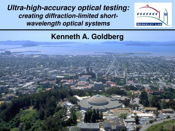
Ultra-high-accuracy optical testing: creating diffraction-limited short-wavelength optical systems. Kenneth A. Goldberg. Ultra-high-accuracy optical testing: creating diffraction-limited short-wavelength optical systems. Kenneth A. Goldberg

E N D
Ultra-high-accuracy optical testing: creating diffraction-limited short-wavelength optical systems Kenneth A. Goldberg
Ultra-high-accuracy optical testing: creating diffraction-limited short-wavelength optical systems Kenneth A. Goldberg Patrick Naulleau, Senajith Rekawa, Paul Denham, J. Alexander Liddle, Keith Jackson, Erik Anderson, K. Bradley, R. Delano, B. Gunion, B. Harteneck, B. Hoef,G. Jones, C. D. Kemp, D. Olynick, R. Oort, F. Salmassi, R. Tackaberry Center for X-Ray Optics,Lawrence Berkeley National Laboratory in collaboration with J. Taylor, G. Sommargren, H. Chapman, D. Phillion,K. Dean, et al.M. Johnson, A. Barty, R. Soufli, S. Bajt,et al.InternationalLawrence Livermore National LaboratorySematech and the EUV LLC and VNL KAGoldberg@lbl.gov, SPIE 2005, 5900-16
Consider two state-of-the-art telescopes SDO — Solar Dynamics Observatory AIA Normal-incidence mirrors Angular Resolution: 0.6”per pixel Please see Soufli, et al. SPIE 5901-24 (Mon) SDO / AIA material courtesy of LMSAL CHANDRA X-Ray Observatory Nested glancing-incidence mirrors Angular Resolution: ~0.5”in 0.5–10 keV NASA / CXC / SAO
Better optics / Better angular resolution is possible Resolution is set by design compromises • Telescope size • Detector-pixel size • Fabrication limits • Collection efficiency • etc. However, thanks to the semiconductor industry,technology for much higher quality lenses is now available in the EUV. So, what does the semiconductor industry want with EUV lenses?
Lithography follows Moore’s Law DRAM half-pitch Intel plans industry plans DRAM – – – – 45 nm 32 nm 22 nm 15 nm 2007 2009 2011 2013 2010 2013 2016 2019 8.6 GB 34 GB 69 GB EUV By 2009–13, mass production of lithographic-quality EUV lenses.
Diffraction-limited EUV optics for photolithography EUV projection lenses may be thehighest quality optical systemsever produced = 13 nm, ~90 eV Mo/Si multilayer-coated fornear-normal incidence: R ≈ 70%(Lawrence Livermore, Lawrence Berkeley, et al.) Diffraction-limited spatial resolution Up to 0.3 NA, ƒ/1.67 Rayleigh resolution: 1.22 / NA 27-nm half-pitch MET projection lens Courtesy J. Taylor, LLNL
Industry-funded EUV projection lithography researchat Berkeley, Livermore, SandiaNat’l Labs patterned reflective mask resist-coated wafer Engineering Test Stand Sandia National Labs. Courtesy, Bill Replogle
Rayleigh criterion /4 P-V 3.35 nm Maréchal criterion /14 rms 0.96 nm Lithographic criterion ~/50 rms 0.27 nm Reaching “diffraction-limited” performance If you can measure it, you can make it. Ultra-high-accuracy optical testing is the key Visible-light and EUV interferometry with sub-Å RMS accuracy.
After After Hubble repair, 1993 COSTAR optic installed Inaccurate interferometry cost NASA $Billions Before Before Hubble Space Telescope Kenneth Goldberg, KAGoldberg@lbl.gov, SPIE 2005, 5900–16
Comparison of slope and roughness requirements SDO — AIA instrument EUV Lithographic Optics Goal 0.5 arcsec Slope error ≤ 5 µradfull aperture Roughness ≤ 4.4 Å1/ƒ = (4 µm, 4 mm) Micro-roughness ≤ 4.4 Å1/ƒ = (9 nm, 4 µm) Goal 32-nm half-pitch Slope error 0.3–1.0 µrad37-Zernikes measured MSFR ≤ 1–2 Åmid spatial-freq. HSFR ≤ 1–2 Åhigh spatial-freq. The specs are several times tighter, and achievable
Pushing visible-light interferometry Livermore scientists developed the PSDI or Sommargren Interferometer Single Mirror • Two beams are launched into a fiber with a time delay. • A pinhole in a mirror creates the test and reference beams. Complete System • One fiber + pinhole at each conjugate. G. Sommargren, J. Taylor, M. Johnson,D. Phillion,H. Chapman, A. Barty, et al. (LLNL) (SPIE 5869–28,30)
the illuminated MET pupil EUV Light transmitted light Kenneth Goldberg, KAGoldberg@lbl.gov, SPIE 2005, 5900–16
PS/PDI interferogram EUV Light ultra-high accuracy Kenneth Goldberg, KAGoldberg@lbl.gov, SPIE 2005, 5900–16
shearing interferogram EUV Light efficient measurement method Kenneth Goldberg, KAGoldberg@lbl.gov, SPIE 2005, 5900–16
A long track record of EUV Interferometry,alignment optimization and imaging at LBNL (since ’93) Berkeley 10x 10xI 10xA 10xB ETS Set-1 ETS Set-2 MET 10xA 10xB2 10xB2 F2X 2-mirror, 10x Schwarzschild objectivesNA ≥ 0.08 ƒ / 6.3 4-mirror, 4x ETS projection opticsNA = 0.1 ƒ / 5.0 2-mirror, 5x MET opticNA = 0.3 ƒ / 1.67 higher resolution time higher quality
ETS Projection Optic: off-axis, large field Work sponsored by the EUV LLC ~1.1-mmask-to-wafer M2 M4 M3 M1
Illumination The 0.3-NA Micro-Exposure Tool:high resolution Work sponsored by International SEMATECH Courtesy of J. Taylor, LLNL Mirrors: Zeiss MET NA = 0.3, ƒ/ 1.67 = 13.4 nm 5x demag. 200 x 600 µm field capable of ≥ 12-nm printing Coating &Assembly:LLNL
MET at-wavelength interferometry and alignment Wavefront measurementduring alignment MET Micro-Exposure Tool central field point astig 0.04 nm coma 0.06 nm sph ab 0.04 nm trifoil 0.14 nm h-o s. 0.37 nm RMS 0.55 nm l/24.5 • EUV interferometry maps the 3-D field of view. • Alignment sets astigmatism, coma, spherical aberration arbitrarily small.
Small tolerances necessitate ultra-high accuracy one nm wavefront quality of best EUV optic to date /24.5 = 0.55 nm EUVL -tool, required wavefront quality /50 = 0.27 nm /135 = ~100 pm EUV interferometer accuracy @ 0.3 NA /330 = 40 pm EUV interferometer accuracy @ 0.1 NA /255 = 53 pm Bohr radius, a0
The keys to achieving ultra-high accuracy 1) Innovative calibration methods (null tests) 2) New interferogram analysis techniques for minimizing phase-measurement errors 3) High-quality “reference” pinholes (Nanowriter) We isolate and measure geometric & systematic errorsources so they can be subtracted.
two-pinhole null-test interferogram system calibration forhigh accuracy Kenneth Goldberg, KAGoldberg@lbl.gov, SPIE 2005, 5900–16
grating null-test interferogram system calibration forhigh accuracy Kenneth Goldberg, KAGoldberg@lbl.gov, SPIE 2005, 5900–16
Developing state-of-the art pinholes for sphericalreference-wave accuracy 150-nm Ni 100-nm Ni TEMPEST-3D Modeling vector E-M field simulations Nanofabrication (Nanowriter) Pinhole-array diffraction object pinhole object pinholes Intensity SEM 100 nm diffraction angle image pinhole Intensity image pinholes 25 nm TEM diffraction angle
The absence of astigmatism confirms accuracy 39-nm isolated lines 0.1-NA ETS optic:lithography at LBNL 13.5 nm wavelength = 0.7, partial coherence DOF = ± 0.5 µm EUV-2D resist, 120-nm thick Coded as 80 nm (1:1)narrowed by exposurebias (x1.4)
0.3-NA MET: Modulation down to ~25 nm 45 nm 35 nm 35 nm 25 nm 30 nm 1.8 mm Rohm and Haas photo-resist R. Brainard, et al. 1.8 mm
We also cross-calibrate the different EUV techniques visible-lightEUV PS/PDIEUV shearing • Inter-comparisons have also improved EUV testing methods.
Conclusions • High-quality EUV optics are available nowlargely due to the development of EUV lithography slope errors: < 1 µrad roughness: ≤ 1–2 Å micro-roughness: ≤ 1–2 Å • Ultra-high accuracy interferometry is required for fabrication and alignment: visible (LLNL) and EUV (LBNL). • We have extended our EUV measurement techniques to 0.3 NA, ƒ/1.67 – Achieved Wavefront quality of 0.55 nm (/24.5). – Demonstrated interferometer accuracy of 1 Å, and below.
Interferometry across the field of view image-plane field measurement [nm] Note: diameter ~ magnitude • Initial measurements showed a large spherical aberration 0.8–0.9 nm • Field measurements are made at 9(x,y) 3(z) = 27 points, 135 interferograms, ~ 3 hours.
Using interferometry to optimize the MET alignment image-plane field measurement [nm] Note: diameter ~ magnitude • Reduced the aberration magnitude to 0.55 nm = /24.5 • Set astig., coma, and sph. ab. to ~/225 – /340
Different kinds of interferometry are used Visible-light• Sommargren Interferometer (LLNL) EUV• Knife-edge (Foucault) testing • Lateral Shearing Interferometry (LSI)- cross-grating technique • Phase-shifting point-diffraction interferometry- ultra-high accuracy - invented at CXRO • Hartmann test- best for low-NA
EUV deviation from a perfect, spherical wavefront = 13.4 nm astigmatism 111 pm coma 47 pm spherical 297 pm trifoil 292 pm 37 RMS 703 pm Kenneth Goldberg, KAGoldberg@lbl.gov, SPIE 2005, 5900–16