Download
1 / 17
310 likes | 751 Vues
JET ENGINE PROPULSION. Chapter 6. Fuel System. TYPICAL FUEL SYSTEM. 1 ST WE WILL LOOK AT A HYDRO-MECHANICAL SYSTEM. TYPICAL FUEL SYSTEM. MECHANICAL DRIVE FROM ENGINE. OIL IN. BOOSTER PUMP. OIL OUT. FUEL DISTRIBUTION AND SPRAY NOZZLES. PUMP OUTPUT CONTROL SIGNAL FROM FCU. FUEL/OIL

E N D
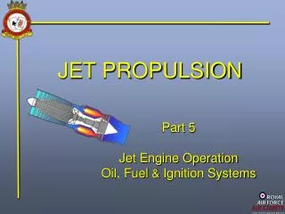
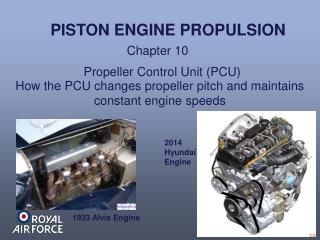
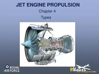
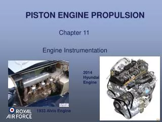
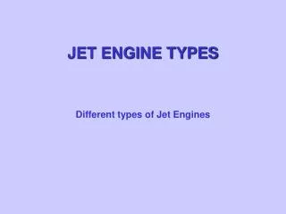
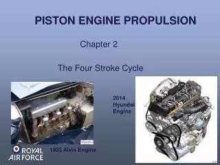
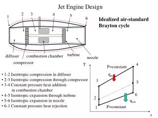
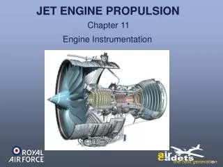
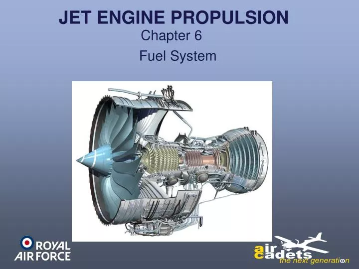
JET ENGINE PROPULSION Chapter 6 Fuel System
TYPICAL FUEL SYSTEM 1ST WE WILL LOOK AT A HYDRO-MECHANICAL SYSTEM
TYPICAL FUEL SYSTEM MECHANICAL DRIVE FROM ENGINE OIL IN BOOSTER PUMP OIL OUT FUEL DISTRIBUTION AND SPRAY NOZZLES PUMP OUTPUT CONTROL SIGNAL FROM FCU FUEL/OIL HEAT EXCHANGER LP FUEL PUMP HP FUEL PUMP WING FUEL TANK LP FUEL FILTER FUEL ‘SPILL’ FLOW FUEL CONTROL UNIT
TYPICAL FUEL SYSTEM LOW PRESSURE PUMP There are two types of Low Pressure Fuel Pumps. Gear Type. Centrifugal Type.
TYPICAL FUEL SYSTEM PUMP FLOW AND RESTRICTION TO FLOW IN CONTROLLER CAUSES PRESSURE TO INCREASE ‘SPUR’ GEARS FLOW OUT Flow Controller GEAR TYPE PUMP
TYPICAL FUEL SYSTEM PUMP INPUT DRIVE LP FUEL IN PUMP IMPELLOR Centrifugal Type. LOW PRESSURE PUMP
TYPICAL FUEL SYSTEM MECHANICAL DRIVE FROM ENGINE OIL IN BOOSTER PUMP OIL OUT FUEL DISTRIBUTION AND SPRAY NOZZLES PUMP OUTPUT CONTROL SIGNAL FROM FCU MULTI PLUNGER (SWASH-PLATE) PUMP FUEL/OIL HEAT EXCHANGER LP FUEL PUMP HP FUEL PUMP WING FUEL TANK LP FUEL FILTER FUEL ‘SPILL’ FLOW FUEL CONTROL UNIT
TYPICAL FUEL SYSTEM HOT OIL IN FCOC PRESSURE RELIEF VALVE COOLED OIL OUT FILTER PRESSURE RELIEF VALVE HOT LP FUEL OUT COLD LP FUEL IN FUEL COOLED OIL COOLER (FCOC) FUEL TUBES OIL BAFFLE PLATES LP FUEL FILTER FILTER PAPER ELEMENT FUEL/OIL HEAT EXCHANGER AND FUEL FILTER
TYPICAL FUEL SYSTEM MECHANICAL DRIVE FROM ENGINE OIL IN BOOSTER PUMP OIL OUT FUEL DISTRIBUTION AND SPRAY NOZZLES PUMP OUTPUT CONTROL SIGNAL FROM FCU FUEL/OIL HEAT EXCHANGER LP FUEL PUMP HP FUEL PUMP WING FUEL TANK LP FUEL FILTER FUEL ‘SPILL’ FLOW FUEL CONTROL UNIT
TYPICAL FUEL SYSTEM SERVO PISTON ‘SWASH’ PLATE SERVO (CONTROL) PRESSURE FROM FCU FUEL PUMPED OUT MECHANICAL INPUT DRIVE FUEL PUMPED OUT KIDNEY PLATE FUEL DRAWN IN OPERATINGPISTON KIDNEY PORT FUEL DRAWN IN MULTI PLUNGER (SWASH-PLATE) PUMP The HP Pump supplies more fuel than is required by the FCU. Normally 110 – 120%.
TYPICAL FUEL SYSTEM MECHANICAL DRIVE FROM ENGINE OIL IN BOOSTER PUMP OIL OUT FUEL DISTRIBUTION AND SPRAY NOZZLES PUMP OUTPUT CONTROL SIGNAL FROM FCU FUEL/OIL HEAT EXCHANGER LP FUEL PUMP HP FUEL PUMP WING FUEL TANK LP FUEL FILTER FUEL ‘SPILL’ FLOW FUEL CONTROL UNIT
TYPICAL FUEL SYSTEM Fuel Control Unit This device controls the fuel delivered to the engine and therefore the power. It adjusts the amount of fuel by taking inputs from various sources. Throttle. Moving the throttle operates a valve to either increase or decrease fuel supply, therefore power. Intake Air Pressure. There is a maximum amount of fuel that can be mixed with a volume of air to burn and the intake air pressure is used to control this. The RPM of the engine is used to govern the max RPM. Engine RPM. Altitude. As altitude increases the air density decreases and the engine idle RPM is increased to prevent a flameout due to lack of power to keep the engine running. Engine Temperature. Used to ensure that the maximum temperature is not exceeded. Any excess fuel is returned to the input side of the HP Pump to be used again.
TYPICAL FUEL SYSTEM Fuel Control Unit The internal workings of a FCU are beyond the scope of our lesson, but the following diagram shows how complicated one is. And this is a simple one.
TYPICAL FUEL SYSTEM NOW WE WILL LOOK AT ELECTRONICALLY CONTROLLED SYSTEMS With an electronically controlled system the engine manufacturer can programme in various parameter limitations and have the electronics monitor and control them. Some of these parameters are: Maximum engine temperature Maximum engine RPM Maximum engine power
TYPICAL FUEL SYSTEM Electronic Engine Controller (EEC) or Engine Control Unit (ECU) This is a computer that controls the operation of the engine and its related accessories that control all aspects of aircraft engine performance, but has a manual override. If the computer fails the engine can be controlled manually. Full Authority Digital EngineControl (FADEC) This is a computer that controls the operation of the engine and its related accessories that control all aspects of aircraft engine performance, but has no manual backup. If the FADEC fails then the engine fails. To prevent this, a FADEC usually has two or three computer channels working simultaneously and comparing with each other to diagnose any computer errors.
TYPICAL FUEL SYSTEM MECHANICAL DRIVE FROM ENGINE OIL IN BOOSTER PUMP OIL OUT FUEL DISTRIBUTION AND SPRAY NOZZLES PUMP OUTPUT CONTROL SIGNAL FROM FCU FADEC Fuel System FUEL/OIL HEAT EXCHANGER LP FUEL PUMP HP FUEL PUMP WING FUEL TANK LP FUEL FILTER FUEL ‘SPILL’ FLOW FUEL CONTROL UNIT FADEC INPUTS TO FCU NO MECHANICAL DRIVE TO THE FCU PURELY ELECTRONIC CONTROL.
TYPICAL FUEL SYSTEM Any questions?