Download
1 / 26
320 likes | 759 Vues
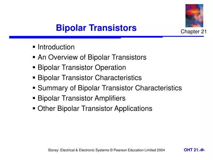
Chapter 21. Bipolar Transistors. Introduction An Overview of Bipolar Transistors Bipolar Transistor Operation Bipolar Transistor Characteristics Summary of Bipolar Transistor Characteristics Bipolar Transistor Amplifiers Other Bipolar Transistor Applications. 21.1. Introduction.

E N D
Chapter 21 Bipolar Transistors • Introduction • An Overview of Bipolar Transistors • Bipolar Transistor Operation • Bipolar Transistor Characteristics • Summary of Bipolar Transistor Characteristics • Bipolar Transistor Amplifiers • Other Bipolar Transistor Applications
21.1 Introduction • Bipolar transistors are one of the main ‘building-blocks’ in electronic systems • They are used in both analogue and digital circuits • They incorporate two pn junctions and are sometimes known as bipolar junction transistors or BJTs • Here will refer to them simply as bipolar transistors
21.2 An Overview of Bipolar Transistors • While control in a FET is due to an electric field, control in a bipolar transistor is generally considered to be due to an electric current • current into one terminaldetermines the currentbetween two others • as with a FET, abipolar transistorcan be used as a‘control device’
Notation • Notation • bipolar transistors are 3 terminal devices • collector (c) • base (b) • emitter (e) • the base is the control input • diagram illustrates the notation used for labelling voltages and currents
Relationship between the collector current and the base current in a bipolar transistor • characteristic isapproximately linear • magnitude of collectorcurrent is generallymany times that of thebase current • the device providescurrent gain
Construction • two polarities:npn and pnp
21.3 Bipolar Transistor Operation • We will consider npn transistors • pnp devices are similar but with different polarities of voltage and currents • when using npn transistors • collector is normally more positive than the emitter • VCE might be a few volts • device resembles two back-to-back diodes – but has very different characteristics • with the base open-circuit negligible current flows from the collector to the emitter
Now consider what happens when a positive voltageis applied to the base (with respect to the emitter) • this forward biases the base-emitter junction • the base region is light doped and very thin • because it is likely doped, the current produced ismainly electrons flowing from the emitter to the base • because the base region is thin, most of the electrons entering the base get swept across the base-collector junction into the collector • this produces a collector current that is much larger than the base current – this gives current amplification
21.4 Bipolar Transistor Characteristics • Behaviour can be described by the current gain, hfe or by the transconductance, gm of the device
Transistor configurations • transistors can be used in a number of configurations • most common is as shown • emitter terminal is common to input and output circuits • this is a common-emitter configuration • we will look at the characteristics of the device in this configuration
Input characteristics • the input takes the form of a forward-biased pn junction • the input characteristics are therefore similar to those of a semiconductor diode
Output characteristics • region near to theorigin is the saturation region • this is normallyavoided in linearcircuits • slope of linesrepresents theoutput resistance
Transfer characteristics • can be described by either the current gain or by the transconductance • DC current gain hFE or is given by IC / IB • AC current gainhfeis given by ic / ib • transconductance gm is given approximately by gm 40IC 40 IE siemens
21.5 Summary of Bipolar Transistor Characteristics • Bipolar transistors have three terminals: collector, base and emitter • The base is the control input • Two polarities of device: npn and pnp • The collector current is controlled by the base voltage/current IC = hFEIB • Behaviour is characterised by the current gain or the transconductance
21.6 Bipolar Transistor Amplifiers • A simple transistor amplifier • RB is used to ‘bias’ thetransistor by injecting anappropriate base current • C is a coupling capacitorand is used to couple theAC signal while preventingexternal circuits fromaffecting the bias • this is an AC-coupled amplifier
AC-coupled amplifier • VB is set by the conduction voltage of the base-emitter junction and so is about 0.7 V • voltage across RB is thus VCC – 0.7 • this voltage divided by RB gives the base current IB • the collector current is then given by IC = hFEIB • the voltage drop across RC is given by IC RC • the quiescent output voltage is therefore Vo = VCC - IC RC • output is determined by hFE which is very variable
Example – see Example 21.2 from course text Determine thequiescent outputvoltage of thiscircuit
Base current is small, so Emitter voltage VE = VB – VBE = 2.7 – 0.7 = 2.0 V Emitter current Since IB is small, collector currentIC IE = 2 mA Output voltage = VCC – ICRC = 10 - 2 mA 2.2 k = 5.6 V
A common-collector amplifier • unity gain • high input resistance • low output resistance • a very goodbuffer amplifier
21.7 Other Bipolar Transistor Applications • A phase splitter
Key Points • Bipolar transistors are widely used in both analogue and digital circuits • They can be considered as either voltage-controlled or current-controlled devices • Their characteristics may be described by their gain or by their transconductance • Feedback can be used to overcome problems of variability • The majority of circuits use transistors in a common-emitter configuration where the input is applied to the base and the output is taken from the collector • Common-collector circuits make good buffer amplifiers • Bipolar transistors are used in a wide range of applications