Download
1 / 30
300 likes | 424 Vues
Machine protection aspects of injection and extraction for the CLIC DR. R. Apsimon. Failure modes. Fast failures Particles hit aperture within few turns E.g. i njection and extraction kicker failures Passive protection needed (collimators, absorbers) Slow failures

E N D
Machine protection aspects of injection and extraction for the CLIC DR R. Apsimon
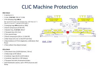
Failure modes • Fast failures • Particles hit aperture within few turns • E.g. injection and extraction kicker failures • Passive protection needed (collimators, absorbers) • Slow failures • Failure slow enough to abort/dump beam before it hits aperture • E.g. magnet power supply failure • Use extraction system to remove beam
Injection kicker failure modes • Inductive adder level failure • 20 levels: supply ~700V each • Consider up to 3 levels failing simultaneously • Assumed to be caused by failure of FETs on level • ~8σ event, so realistic worst-case scenario. • Total inductive adder failure • Likely to be due to a trigger timing error • ALL particles considered dangerous and hit aperture shortly downstream of injection • Injection collimator designed to capture full 6σ beam (+ tolerances)
Collimator considerations [1] • Number of σ that can pass through aperture δ = alignment tolerance = 2mm A1/2 = physical half-aperture Acceptance calculations at injection emittance
Collimation considerations [2] • Beam aperture critical in injection/extraction regions • Use absorbers to protect septa (fixed position) • Collimators to protect rest of machine (moveable) • Collimation scheme depends on whether septa are in vacuum or not
Septa in vacuum: H-plane Red: kicker Orange: quads in injection cell Blue: septum edge Brown: quads in matching cell Purple: stored beam Green: Injected beam (total kicker failure) Dark green: region of beam removed by first collimator
Septa not in vacuum: H-plane Red: kicker Orange: quads in injection cell Blue: septum edge Brown: quads in matching cell Purple: stored beam Green: Injected beam (total kicker failure) Dark green: region of beam removed by first collimator
Comments on collimator plots • Beam envelope • 6σ envelope ± 2mm tolerance • First collimator • Needed to stop particles hitting aperture before reaching second collimator • Second collimator • Designed to completely capture beam for total kicker failure
Comparison of schemes • Septa in vacuum • Smaller beams; good aperture clearance • >4 m reduction in total length of DR • This is almost entirely drift length • Septa not in vacuum • Efficient collimation
Tracking simulations • Tracking done for failure of 3 inductive adder levels • 1000 particles for 100 turns • Uniform random number generators: 6σ± 2mm phase space • Polar coordinates to create oval beams • 340 “dangerous” particles • Exceed 6σ± 2mm phase space of nominal orbit All particles captured by absorbers + collimators; no losses in kickers or elsewhere. Remaining 0.9% of particles on edge of phase space limit and survive for many turns.
Phase space: no collimation Phase space plot at second injection collimator
Phase space coverage: 1 turn Blue: phase space of nominal orbit Green: Phase space of poorly injected beam (3 levels failed) without collimation Red: Phase space of poorly injected beam (3 levels failed) with collimation Black: Phase space confined by collimation
Phase space coverage: 2 turns Blue: phase space of nominal orbit Green: Phase space of poorly injected beam (3 levels failed) without collimation Red: Phase space of poorly injected beam (3 levels failed) with collimation Black: Phase space confined by collimation
Phase space coverage: 3 turns Blue: phase space of nominal orbit Green: Phase space of poorly injected beam (3 levels failed) without collimation Red: Phase space of poorly injected beam (3 levels failed) with collimation Black: Phase space confined by collimation
Phase space coverage: 4 turns Blue: phase space of nominal orbit Green: Phase space of poorly injected beam (3 levels failed) without collimation Red: Phase space of poorly injected beam (3 levels failed) with collimation Black: Phase space confined by collimation
Dump system considerations • Latency • How many turns before beam can be dumped? • Location and space constraints
Breakdown of latency • Signal time of flight to dump kicker • ~1μs • Latency of electronics • <1μs • Kicker rise time • ~700ns • Time for 1 turn of ring (circumference: 400-450m) • 1.3-1.5μs • ~2-3 turns of ring required to dump beam
Location + space constraints • Avoid • Regions with synchrotron radiation • High dispersion regions • Near injection or extraction only suitable places. • Dedicated dump cell? • Would add ~10m in each straight section • Unacceptable increase in length • Can extraction cell be used as dump system?
Technical challenges • Kicker must fire in two modes • Extraction mode (±12.5kV) • Dump mode (±17.5kV) • Need to extract beam with injection emittance • Separate dumped beam from extracted
How to achieve 2 kicker modes • Separate inductive adder into 2 banks of levels • “Bank 1” contains 20 levels • “Bank 2” contains 8-10 levels • Extraction trigger discharges Bank 1 • Dump trigger discharges Banks 1 and 2
Kicker triggering Bank 1 Bank 2 Bank 1 Bank 2 Trigger select Trigger select “Extract” “Dump”
Consideration of damping time [1] • Time needed to damp beam: • Injection: 54 μm rad (x), 1.3 μm rad (y) • Extraction: 500 nm rad (x), 5 nm rad (y) • Equilibrium: 470 nm rad (x), 4.8 nm rad (y)
Consideration of damping time [2] • ~8.5 damping times to reach design • 17ms(injection period 20ms) • How long to charge inductive adder? • Currently unknown, estimate ~90% at injection • Add levels in Bank 2 to compensate missing charge? • Reduce storage time by ~1 damping time? • 4% increase in extraction emittance; acceptable?
Kicker failure modes • Extraction mode • Both banks fire: beam dumped → safe • Bank 1 fires: beam extracted → safe • Bank 2 fires: beam absorbed by septum absorber and collimator → safe • Neither bank fires: beam remains in ring • Dump mode • Both banks fire: beam dumped → safe • Bank 1 fires: beam extracted → NOT SAFE • Bank 2 fires: beam absorbed by septum absorber and collimator → safe • Neither bank fires: beam remains in ring
Separate ext and dump beams • Start of extraction line • Kicker gives larger deflection to dumped beam • Use defocussing quad to further separate beams • Septum magnet to separate ext and dump lines • Use same septa design as in extraction system
Comments on design • Septa in vacuum? • Easier if extraction septa NOT in vacuum • More lever-arm; less length needed to separate beams • Twiss parameters more controllable • Final quad needed in dump line • Control spot size at dump block
Radiation length • Need minimum 5 rad. lengths for 2.86 GeV e- • Use 10 rad. lengths for dump block • Use 5 rad. lengths for absorbers and collimators Higher density means more back scattering, but shorter radiation length
Material choice • In DR, space is limited • short radiation length and low back-scattering • Use titanium: ~20cm for collimators and absorbers • Dump block • Space not limited • Use carbon for dump block • Surround block in higher mass material (e.g. lead) to contain radiation.