Download
1 / 30
300 likes | 425 Vues
The Post-linac Collimation System of CLIC: Machine Protection Aspects. Javier Resta Lopez IFIC (CSIC-UV), Valencia, Spain In collaboration with J. L. Fernandez-Hernando, A. Latina and R. Tomas. Machine Protection workshop 6-8 June 2012, CERN, Geneva. Introduction.

E N D
The Post-linac Collimation System of CLIC:Machine Protection Aspects Javier Resta Lopez IFIC (CSIC-UV), Valencia, Spain In collaboration with J. L. Fernandez-Hernando, A. Latina and R. Tomas Machine Protection workshop 6-8 June 2012, CERN, Geneva
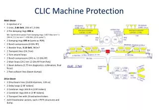
Introduction • The main functions of collimation systems for high energy colliders: • Reducing detector background at the interaction point • Protecting the machine by minimising the activation and damage of sensitive components • In the BDS of the future linear colliders (ILC and CLIC) there are two collimation sections: • Betatron collimation: transverse halo cleaning • E collimation: collimation of particles with high energy deviation • In this presentation we focus on the machine protection function of the CLIC collimation system
Introduction • Machine protection in BDS usually relies on: • Emergency extraction kickers and dumps (fast abort systems) • BPMs and BLMs for abnormal operation detection, and interlock systems • Passive protection: collimation system, masks • The CLIC E collimation system is conceived to fulfil a function of passive protection of the BDS against miss-steered beams • Energy collimation depth determined by failure modes in the linac • The conventional collimation systems are based on mechanical collimation using spoilers (scrapers) and absorbers. It could include several stages
Beam delivery systemCLIC BDS vs ILC BDS CLIC BDS 3 TeV CM ILC BDS 0.5 TeV CM [Deepa Angal-Kalinin/James Jones] In CLIC BDS the E collimation system is upstream of the betatron one. The main reason for choosing this is because energy errors generated by failure modes in the CLIC main linac are expected to be much more frequent than large betatron oscillations with small emittance beams
CLIC baseline BDSOptics Energy collimation: Protection against miss-steered or errant beams with energy errors ~> 1.3%. E-spoiler half-gap: ax=Dxδ=3.51mm 4 pairs of spoilers and absorbers in x,y plane to collimate at IP/FD phases
Collimator parameters Beryllium has been considered as a good material candidate for the E-spoiler. Its high electrical and thermal conductivity with a large radiation length compared with other metals makes Be an optimal candidate. Energy colllimators Betatron collimators
Failure modes • Investigation of failure modes in the CLIC main linac which could generate significant energy deviation, in such a way that the beam hits the energy spoiler • For example: Injection phase error, RF breakdown, missing drive beam, beam charge error • Tracking simulations LINAC + BDS assuming failures between two pulses. Assuming nominal beam parameters and a perfect linac lattice (no additional lattice imperfections) • Thermo-mechanical characterisation of the energy collimators using the output beam distribution from tracking simulations, and the codes FLUKA (energy deposition and temperature rise) and ANSYS (mechanical stress)
Failure modes • Injection phase error: Beam centroid trajectory in the BDS for different injection phase errors For phase error ~> +5o and <~ -3o the beam hits the energy spoiler (ESP)
Failure modes • Injection phase error (example 1): Temperature increase along the spoiler For -5o phase error, transverse beam distribution at ESP ΔTpeak=210 K FLUKA Beryllium spoiler model ANSYS σx=757.72 μm σy=26.45 μm Emean=1463.8 GeV ≈1% full energy spread Equivalent stress The equivalent stress reaches a peak (300 μs after the beam impact) which surpasses the fracture limit (> 370 MPa)
Failure modes • RF cavity fail: Beam centroid trajectory for different number of RF structures switched off in the last section of the main linac
Failure modes • RF cavity fail (example 2): Temperature increase along the spoiler 1500 cavities switched off in the last section of the main linac. Transverse beam distribution at ESP ΔTpeak=35 K FLUKA Beryllium spoiler model ANSYS σx=1 mm σy=25.4 μm Emean=1471 GeV ≈1% full energy spread Equivalent stress In this case, the equivalent stress is below the fracture limit, but it stabilises near the tensile yield strength (deformation limit, 240 MPa)
Failure modes • Results show that, considering the previous failure scenarios and the nominal beam parameters, it may be difficult to avoid the spoiler fracture or a permanent deformation of the spoiler surface • In order to reduce the risk of damage to the spoiler, we are considering the following alternatives: • Alternative materials • Alternative geometric structure • Alternative optics: nonlinear passive protection
Beampipe wall or spoiler support Vacuum L L Ti-alloy or Be Beam axis Alternative spoiler design • “Hollow” spoilers • 2L is the minimum length of material that the beam has to see in order to obtain the • necessary angular divergence Θ by MCS. In this way the beam spot size is increased • at the downstream absorber position in order to avoid its damage or fracture. • The empty inner part of the spoiler could accommodate a water cooling circuit or • some other kind of cooling system
Beampipe wall or spoiler support SiC foam Ti-alloy or Be Beam axis Alternative spoiler design • “Semi-hollow” spoilers Cu We plan to study the thermo-mechanical characteristics of these spoiler designs using the codes FLUKA and ANSYS (following the same procedure as for examples 1 and 2).
collimators S1 S2 Sextupole 1 Sextupole 2 R (s1→ s2) Nonlinear passive protectionBasic concept • Use a nonlinear magnet (e.g. sextupole, octupole), which somehow plays the role of a spoiler (or primary collimator), to increase the beam spot size at the downstream collimators for a beam with mean energy offset ~> energy collimation depth • Cancellation of optical aberrations using a second nonlinear element • For CLIC we have studied an E collimation system based on a pair of skew sextupoles of relatively moderate strength
Nonlinear passive protection In the past … Concept of Magnetic Energy Spoiler (MES) for TESLA [R. Brinkmann et al., TESLA-01-12 (2001)] • According tracking simulations: • The beam area is increased by a factor of 6 wrt the linear beam at the • momentum spoiler position ! • However, significant luminosity degradation !
CLIC nonlinear energy collimation system • Conceptual layout Optical optimisation: To cancel higher order aberrations a skew octupole and a normal sextupole have been added downstream of the second skew sextupole.
CLIC nonlinear energy collimation system • Optical constraints to cancel geometric nonlinear terms between two skew sextupoles: • R12=0, R34=0, |R11|=|R33|, |R22|=|R44| • Phase advance: • μx(s1→s2)=nxπ, μy(s1→s2)=nyπ, where nx, nyare integers • Relation between the strength of the two skew sextupoles: • whereKs1and Ks2 are the normalised strength of the 1st and 2nd sextupole respectively, and βx • and βx2are the horizontal betatron function at the 1st and 2nd sextupole position respectively • We use –I transform in both x and y planes between the sextupoles, which is a special case of • the previous conditions: nx=1, ny=1, βx1= βx2,βy1= βy2, αx1= αx2, αy1= αy2. Therefore, Ks1=Ks2 • In addition, to cancel chromatic and chromo-geometric aberrations between the skew sextupole • pair: Dx1= –Dx2
CLIC nonlinear energy collimation system • Optical layout BDS
CLIC nonlinear energy collimation systemBeamline performance BEAM IP s1 s2 At 1st skew sextupole At spoiler At energy collimation system exit At IP • Multi-particle tracking simulations: • Using the code MAD • 50000 macroparticles tracked through the CLIC BDS • Gaussian beam distributions for the transverse phase space • 1% full energy spread (uniform distribution)
≈2% luminosity loss ≈35% luminosity loss Ks=8 m-2 CLIC nonlinear energy collimation systemBeamline performance • Luminosity Relative Luminosity vs skew sextupole strength K(skew octupole) = -2400 m-3 K(normal sextup.) = -0.4 m-2 With optimisation (additional nonlinear elements)
CLIC nonlinear energy collimation systemBeamline performance • Luminosity Energy bandwidth: Relative peak luminosity (within 1% of Ecm) vs. beam energy offset δ0=ΔE/E0 Both linear and nonlinear systems present a comparable bandwidth !
CLIC nonlinear energy collimation systemBeamline performance • Beam size at spoiler position Transverse beam spot size vs. skew sextupole strength for different beam energy offsets Transverse beam peak density vs. skew sextupole strength for different beam energy offsets For 1.5% mean energy offset, the nonlinear energy collimation system (using Ks=8 m-2) increases 2 times the beam spot size (reduces 4 times the transverse peak density) at the energy spoiler wrt the baseline linear collimation system
Conclusions • The CLIC post-linac E-collimation system will play an essential role in protecting BDS against miss-steered beams • The E-collimation depth is determined by failure modes in the main linac • In order to improve the current baseline collimation system design, it is necessary to investigate and identify failure scenarios which could be critical in terms of collimator damage • Concretely we have studied failures which could generate a significant beam energy deviation, in such a way that the beam directly impacts on the energy spoiler • Tracking simulations LINAC + failure modes + BDS + thermo-mechanical analysis of the spoiler (FLUKA + ANSYS) for CLIC are in progress • Preliminary results show that it may be difficult to avoid fracture or permanent deformation of the spoiler with the current baseline design • Further studies have to be performed to evaluate the real magnitude of the fracture and the deformation. For example, a permanent deformation could translate into an increase of the roughness of the spoiler surface, hence increasing wakefield effects • We are currently investigating alternative spoiler designs and alternative optical layouts, such as a nonlinear collimation system, to reduce the risk of damage to the energy collimators
MPS strategy for BDS • The MPS strategy is determined by the bunch train time structure • ILC: • The relative long pulse and large bunch spacing allow that a fault can be detected and • the pulse aborted within the train itself. • An errant or miss-steered beam could be aborted at the beginning of the BDS by using a • fast kicker system (rise-times ~100 ns) to send the beam to an emergency dump • This fast abort system is intended to protect the BDS providing that the collimation • system can survive one bunch
MPS strategy for BDS CLIC: • In case of fast failures in the main linac (at microsecond time scales), the extremely short bunch spacing (0.5 ns) and small pulse length (156 ns) make the fault detection and abortion within the same train very difficult (not attainable with current kicker technology) • Then a first miss-steered train is detected and not extracted by the emergency kicker at the exit of the main linac, and the subsequent pulses could be extracted by the emergency abort system . After the detection of abnormal operation (in the pulse-to-pulse interval) an interlock system could stop operation • In this case, the protection of the BDS relies mainly on the collimation system (passive protection). The E-collimation system is designed to withstands the impact of, at least, a bunch train.
Failure modes • RF cavity fail: In terms of spoiler damage, the case of the total failure of a series of RF cavities at the start of the linac is less critical, since the energy spread increases and the beam suffers a rapid filamentation Transverse beam distribution at ESP 300 RF structures OFF 400 RF structures OFF ~55% particles lost along the linac and the diagnostic section of the BDS
Failure modes • Beam charge error: Beam centroid trajectory in the BDS for different beam charge errors in the range [-50%, +50%] In this case, the resulting energy deviation is relatively small for the beam to be caught in the energy spoiler
Parameters for the CLIC nonlinear energy collimation Spoiler parameters Skew sextupole parameters