Download
1 / 16
160 likes | 309 Vues
Post-Linac Collimation. NLC Collaboration Meeting FNAL, June 2000. P. Tenenbaum. Overview of Collimation. A serious problem for all high-performance colliders # of collimators tends to increase over machine lifetime!

E N D
Post-Linac Collimation NLC Collaboration Meeting FNAL, June 2000 P. Tenenbaum
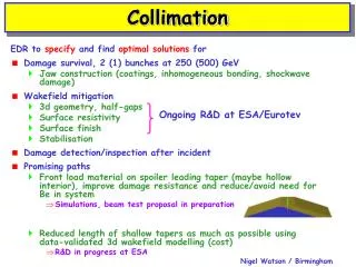
Overview of Collimation • A serious problem for all high-performance colliders • # of collimators tends to increase over machine lifetime! • A nightmare for NLC -- must be addressed in systematic, machine-wide fashion • bunch length collimation in DR extraction? • 5-D system at end of pre-linac (8 GeV) • part of machine protection system • Post-linac 5-D system • part of machine protection system • Collimators in FF high-b points • Assorted detector masking • Possible sacrificial collimators
Collimate large-amplitude particles which make backgrounds x, x’, y, y’, d Do not generate bkgds from nonlinearities Do not generate bkgds from muons Do not generate bkgds from collimated primary particles Minimize collimator wakefield effects Do not degrade luminosity Protect FF and LCD from beam core Collimators must survive ~1 year ops System design must be OK for CM energies from 0.1 1.0 TeV Pulsed linac extract with diagnostics Properties of Post-Linac Collimation System
Collimation Depth • Set by SR emission in final doublet • CD-1: 8 sx by 40 sy at 1 TeV CM • Need to follow up on: • aperture at lower energies? • New FF optics changes aperture? • masking and soft bend set up ok?
Sources of Beam Halo • Per 1012particles (1 train), we expect: • DR/RTL/Compressor: ? • Main Linac Wakefields: <107 (Tor) • Captured Dark Current: ~104 (Brinkmann) • Multipoles in main linac: ? • Linac coulomb/compton ~104 (Tor) • Linac mistuning ? • BDS coulomb/compton ~103 (ZDR) • SLC experience: < 1% of beam in halo (most from DRs/RTLs?) • Expect some improvement from pre-linac collimation • Present design assumes 109 halo particles, should try to collimate at 10-6 level (transmitted halo ~ repopulation halo)
ZDR System (1996) • Passive survival of 1 bunch-train impact • requires spoilers/absorbers • requires big betatron functions, sextupoles... • Collimate 5 sx, 35 sy, 4% off-energy • interleaved collimators and lots of them • Jitter amplification: ~0.25 s in quadrature • x, d combined collimation (not independently tunable) • IP phase collimation looser • 2 phases x 2 planes x 2 times collimation • Long (2.5 km) system far from IP • hard to operate but good for muon bkgds
ZDR System Problems • Long system with many elements • Tight tolerances • Micron level magnet misalignments steered beam into downstream collimators • Energy collimation too loose • Loose collimation in IP phase does not work • off energy particles have phase migration 1999: Time for a New Approach!
Collimator Damage Options • 4-D parameter space: • tolerances • collimator survival • also • muon backgrounds • tail populations • ZDR design pushed tolerances • Redistribute the pain—ease tolerances with engineering design! Single Pulse Collimator Damage Conventional collimators not damaged Never ZDR ‘Consumable’ collimators damaged 1000x per year Seldom ‘Renewable’ collimators damaged each pulse Always Looser Tighter Optics Tolerances
Consumable Collimator • Rotating-wheel spoiler • many degrees of freedom needed • positioning accuracy • prototype soon • Can be hit by beam core 1000x per run • Absorbers can be far from core (~mm), hard to hit • Allows optics with smaller beams
The New Approach • Separate energy and betatron collimation • energy still needs passive protection • maximize h/b ratio • collimation depth to 1%? • Equal coll depths for IP and FD phases • permits arbitrary phase advance to IP • Consumable spoilers in betatron coll • smaller beam sizes • min coll aperture limited by image current heating • DC heating from halo also an issue
Energy Collimation • Spoiler/Absorber system used for passive survival • Be spoilers (0.5 RL), Ti/Cu absorbers (20 RL) • 20 cm hmax • 1% energy collimation possible in principle • Looser tolerances • R34 max ~200 m, not 41 km • Emittance dilution from SR ~5% at 1 TeV CM • slightly larger than old system (4%) • Post-linac energy diagnostic and pulsed dump • Collimator wakefield cancellation • 2 sets of spoilers/absorbers at -I in betatron optics but equal dispersions -- to 1st order wake kicks cancel • 2” OD vacuum chamber • allows 10% off energy beam to be handled • really good pumping!
Betatron Collimation • 2 phases x 2 planes x 2 times collimation • 0.5 RL spoilers (~200 mm half gap at 1 TeV CM) • 20 RL absorbers (1 mm half aperture @ 1TeVCM) • 5.7 sx x28 sy collimation, 90/270 deg lattice • gives correct collimation depth at 45 degrees in beta phase • can loosen coll depth if 45/135 deg lattice is used • Smaller beta functions, looser tolerances • Ti/Cu absorbers -- okay as long as beam goes thru a spoiler first! • Jitter amplification: around 46% • ZDR system had almost 70% • (0.46) x (0.37 s incoming jit) = 0.17 s added jitter • tolerance for entire BDS is 0.25 sy
Halo transmission: ~10-5, goal is 10-6 dependent on halo distribution Primaries in 2nd half of betatron system: 107--108, goal is 107 Power hitting quads is 1.3% of halo (total) -- OK Primary/secondary beam size on absorber: > 1.5 mm, OK Total bandwidth ~3%, goal is 4% Muons in LCD: too many, but can add muon spoilers (presently 2 per side) Performance Factors
Conclusions • New collimation system proposed for NLC post-linac region • 1.2 km long • looser tolerances than ZDR scheme • Looks promising • Many detailed calcs/studies, which have just begun!