Download
1 / 17
170 likes | 256 Vues
Update on ORNL Diagnostic and Tungsten Armor Efforts. Keith Leonard, Glenn Romanoski, Lance Snead Oak Ridge National Laboratory Nalin Parikh UNC, Chapel Hill Shahram Sharafat Out West. Presented at the HAPL Meeting PPPL, Princeton, NJ December 12-13, 2006. Carbon Buildup In W-Armor.

E N D
Update on ORNL Diagnostic and Tungsten Armor Efforts Keith Leonard, Glenn Romanoski, Lance Snead Oak Ridge National Laboratory Nalin Parikh UNC, Chapel Hill Shahram Sharafat Out West Presented at the HAPL Meeting PPPL, Princeton, NJ December 12-13, 2006
Carbon Buildup In W-Armor Carbon Implantation Profile • Model Carbon diffusion with Temperature evolution (t=0 use spatial Carbon implantation profile and “end of shot” temperature profile) Carbon Concentration Within ~ 10 days of operation C-concentration = W-concentration
Objectives for performing carbon ion implantation in tungsten • C ions (~ 0.5 MeV) will be implanted in W samples heated to IFE surface-relevant temperatures (~2000C). Tungsten samples will include two plasma sprayed tungsten materials and other candidates used for He implantation. • Models for carbon implantation will be validated and refined. • Response of W to high-dose carbon implantation and tungsten carbide formation will be assessed. • Mobility of carbon through porous, plasma sprayed microstructures will be quantified. • Combined effect of C and He implantation will be assessed.
Development of VPS W/LAF O C Interface F82H Steel Tungsten 20.0keV 10.0kX 1.0 µm • We are considering the VPS W/LAF sufficiently mature. Have withstood 10,000. • Continuing long term aging of interface (currently > 10,000hr) • Next series of thermal fatigue tests planned for long-term aged and carbon implanted material.
The flux of carbon ions into the W armor surface ensures the formation of tungsten carbide • The formation of W2C and WC is likely to cause near surface dilatation and spallation damage. • A tungsten carbide reaction zone will likely affect He damage. • Carbon ions near the surface are a potential source of Carbon to the W/FS interface.
Polycrystalline tungsten was implanted with carbon ions by UNC at RT followed by annealing at 2000ºC for 5 min.XRD analysis confirmed the formation of W2C Under 1 micron C dose: 1.4 E19 c/cm2 @ 100K eV
Implanted surface Milling artifacts from FIB Grain #1 Grain #2 Depth into sample Grain #5 Grain boundaries Grain #3 Grain #4 Carbon Implanted Tungsten • Step 1: • Carbon implantation • Polycrystalline W • 1.4x1019 cm-2 • Room temperature • Step 2: • Thermal anneal • Electrical resistance heating • 2000ºC • 5 minutes Cross-section from sample milled out by focused-ion beam (FIB) for TEM examination.
Implanted surface Milling artifacts from FIB Grain #1 Grain #2 Depth into sample Grain #5 Grain boundaries Grain #3 Grain #4 Carbon Implanted Tungsten • Particles observed along grain boundaries. • Discontinuous along boundaries. • Typically 100 to 200 nm in size. • Observed to a depth of 7.6 mm from surface.
Depth into sample Carbon Implanted Tungsten • Particles observed in grain (#1) near implantation surface. • Needle-like, consisting of segments. • Up to 2 mm long, 25 nm thick. • Observed to a depth of 2.6 mm from surface. Implanted surface Milling artifacts from FIB Grain #2 Grain #1 Grain #5 Grain boundaries Grain #3 Grain #4
Implanted surface Milling artifacts from FIB Grain #1 Grain #2 Depth into sample Grain #5 Grain boundaries Grain #3 Grain #4 Carbon Implanted Tungsten • Particles observed along grain boundaries. • Discontinuous along boundaries. • Typically 100 to 200 nm in size. • Observed to a depth of 7.6 mm from surface.
Issue: He implantation of aluminum mirrors is used as a first approach at simulating the changes in optical properties and performance of mirrors in the IFE under irradiation. The degree of surface roughening and the resulting degradation in optical performance of metal mirrors for the IFE as a result of charged particle implantation and neutrons is an important issue that has not been well addressed. Material: 1 inch diameter electrodeposited aluminum, 250 micron thick, on 6061-T6 aluminum substrate – manufactured by AlumiPlate Inc. Diamond turned mirror surface, between 40 to 46 Å surface roughness-turned by II-VI Infrared. He Implantation: Performed by Nalin Parikh and Shon Gilliam, UNC-Chapel Hill. Use of beam mask allowing for multiple implantation tests per sample. 110 keV, 4He implantation. 1x10¹⁹, 1x10²⁰ and 1x10²¹ He/cm2 0, 30 and 60º angle of incidence. Room temperature implantation. Implantations produce a range of damage from 0.01 to 2 dpa at 100 nm below the surface for the various conditions based on SRIM code simulation. Current Status of Work: Samples received at ORNL for optical measurements. Some discoloration on the surface for the 1021 He/cm2 locations. Samples currently Optical ellipsometry techniques for changes in quality. Atomic Force Microscopy for changes in surface roughness. SEM examination of surface roughness. Helium Implantation Studies of Simulated Irradiation Damage to Aluminum Mirror Performance Sample 1 1x10¹⁹ He/m2 0º tilt 1x10²¹ He/m2 30º tilt 1x10²⁰ He/m2 0º tilt 1x10²⁰ He/m2 30º tilt 1x10²¹ He/m2 0º tilt 1x10¹⁹ He/m2 30º tilt Sample 2 1x10²¹ He/m2 1x10²⁰ He/m2 1x10¹⁹ He/m2 All at 60º tilt
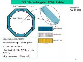
Update: Irradiation Damage on Dielectric Mirror Performance Dielectric Mirrors • Films deposited by E-beam with ion-assist on sapphire substrates. • Quarter wavelength bi-layers of HfO2 / SiO2, HfO2 / Al2O3 and Al2O3 / SiO2. • Quarter wavelength monolayers of HfO2 (26.9 nm thick), Al2O3 (36.5 nm thick) and SiO2 (40.5 nm thick) on sapphire. Tasks • Phase 1, FY-06: He implantation • Collaboration with Nalin Parikh (UNC) • Tests conducted on monolayer films only to evaluate film/substrate interactions. • Phase 2, FY-07: Neutron irradiation • Collaboration with T. LaHecka (Penn. State) and M. McGeoch (Plex Corp.) • Irradiation at High Flux Isotope Reactor and post irradiation evaluation at ORNL.
Changes to Monolayer Thin-Films Following Helium Ion Implantation Issue: Multilayered dielectric mirrors could significantly improve transmission of reflected electromagnetic energy, but little is known about their longevity and performance in IFE relevant environments. Preliminary work on performance of dielectric mirrors under neutron irradiation has been inconclusive. This is due in part to the behavior of the constituent film layers under irradiation and the film/substrate interface interactions not being understood. Material: E-beam / ion-assist deposited films of quarter wavelength thick: • Al2O3 (36.5 nm thick) on sapphire • SiO2 (40.5 nm thick) on sapphire • HfO2 (26.9 nm thick) on sapphire • Un-coated sapphire for control He Implantation: • Phase 1 of study (Phase 2,HFIR Neutron Irradiation). • Performed by Nalin Parikh and Shon Gilliam, UNC • Use of beam mask allows multiple implantation tests. • 110 keV, 4He implantation, 0º tilt, room temperature. • 1018, 1019, 1020 and 1021 He/m2. • Implantation conditions produce 0.001 to 1 dpa of damage at the film/substrate interface – SRIM calculations. He implantation mask Current Status of Work: • General inspection of films by SEM showed no signs of delamination or blistering. • Atomic force microscopy carried out to determine changes in surface roughness and step height differences between implanted and non-implanted regions. • Optical examination by ellipsometry techniques for changes in quality pending.
Changes to Monolayer Thin-Films Following Helium Ion Implantation • AFM data. • SiO2 monolayer on sapphire. • 1x10¹⁸ and 1x10¹⁹ He/m2 dose. • No significant difference observed on film surface. • Ellipsometry and high-resulution SEM underway
Nalin et al. has performed Carbon implantation on three polycrystalline tungsten samples at ambient temperatures followed by annealing at 2000C for 5 minutes. The samples include the following C+ Doses: I believe all are 100KeV implantation voltage. Nalin can confirm. GM2 1.4E19 cm-2 GM3 3.6E17 cm-2 GM4 5.4E17 cm-2 X-ray diffraction confirms W2C formation in all samples. The diffraction pattern attached for GM2 shows some shift from the perfect W2C lattice due to non-stochiometry according to Burl Cavin (see phase diagram). Keith has confirmed the presence of W2C in the GM2 sample.
Effects of Carbon Implantation (ORNL/UNC/UCLA) • Issue: About 6.8x10¹⁹ per shot Carbon atoms are released from the 365 MJ Target (10 m Chamber): • ~1.7 appm per shot Carbon in Tungsten in about 1x10⁶ shots C/ W ~ 1.7 (1.2 days @ 10 Hz) • ~0.7 appm per shot Carbon in SiC in about 1x10⁶ shots C/ W ~ 0.7 (1.2 days @ 10 Hz) • Goals: (1) Investigate the Behavior of Carbon Implantation : • Free or bound Carbon (WC and W2C) ? • Release of Carbon from surface or Diffusion of Carbon toward W/Steel Interface ? (2) Investigate Helium Release from Carbon Implanted Region : • Helium release • Experiments:Follow Sample Handling Procedure • (1) UNC Carbon Implantation (Single-X W) Steady State followed by 1 Annealing Cycle: • Implantation at T = 850°C, <0.5 MeV • Total C-Fluence = 1.6x10²² C/m2 (eq. to ~3x10⁵ shots or ~ ½ day at 10 Hz) C/ W ~ 0.5 • Anneal at 2000°C for ~430 sec (total time above 1000 C for ~3x10⁵ shots) • Determine depth profile and density of Carbon & Perform Hardness measurements (2) UNC Helium Implantation (use Carbon exposed SX-W). Step wise He followed by 2000 C annealing: • Implant 1x10193He/m2 at 850°C, flash anneal at 2000°C in 1000 or 100 steps • Determine Helium release and depth profile. • Modeling: • Modify Carbon Diffusion model (UCLA) to include WC and W2C formation • Add Carbon Implantation/Carbide Formation to the HEROS code He model (UCLA): • Account for large damage rates caused during C-implantation and short time at T.