Download
1 / 39
400 likes | 403 Vues
Extending LANs. Based on Chapter 11 in Computer Networks and Internets. Size Limitations. Recall that the combination of protocol and wiring scheme places size restrictions on a LAN Ethernet using 10Base5 (thick) allows segments up to 500 m

E N D
Extending LANs Based on Chapter 11 in Computer Networks and Internets
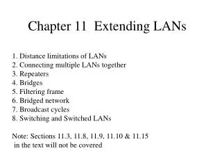
Size Limitations • Recall that the combination of protocol and wiring scheme places size restrictions on a LAN • Ethernet using 10Base5 (thick) allows segments up to 500 m • FDDI (Fiber Distributed Data Interface) allows a single ring to be 100 kilometers (62 miles)
Reason One • Attenuation and interference: • The farther a signal travels, the more it attenuates (weakens). If the amplitude is reduced, the signal-to-noise ratio may decrease. And the information may be lost in the noise. • The farther a signal travels, the more likely it is to experience interference (noise) — other unwanted waves adding to it. • Increasing the amplitude would help but that requires additional power and thus increasing cost.
Reason Two • Sharing Speed: • The longer a token ring (and the more computers on it), the longer it takes before it is a given computer’s turn to transmit. • The longer a bus (and the more computers on it), the more likely that two computers will transmit simultaneously causing a collision (CSMA/CD).
Fiber-Optic Extensions • The attenuation/interference limitation can be overcome by changing the medium: wire fiber optic cable. • Recall fiber optic cable has a much higher bandwidth and is much less susceptible to interference. • Building a LAN entirely of fiber is expensive. • One of the reasons FDDI did not become more widespread is because of its cost. • But fiber optic cable can be used to extend certain connections in a LAN.
Fiber Optic Extensions (Cont.) • The connection between the computer and the bus could be partially spanned by fiber optic cable. • Electrical signal goes to a fiber modem. • The fiber modem converts the signal into an optical form for transmission over the optical fiber. • A second fiber modem receives the optical signal and converts it back to an electronic signal. • The electronic signal is placed on the bus in the usual way.
Fiber Extension (Fig. 11.1) Note as shown above one is adding a single computer that is a large distance from the rest of the network. But this idea can be extended.
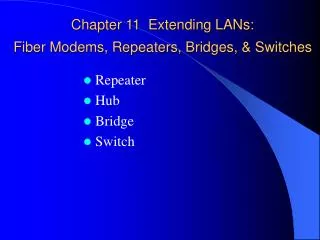
Repeater • Another solution to the attenuation/interference problem is to use a repeater. • A repeater receives a signal, amplifies it, and then retransmits (forwards) it. • Repeaters are used between segments of a local area network (LAN). • Segments have a fixed maximum length. • Repeaters are also used in WANs, both wired and wireless.
Repeater (Cont.) • In its simplest version an analog repeater simply amplifies the signal it receives. • Therefore, if any noise has corrupted the signal, that noise is also amplified. This is the best a repeater can do with an analog signal. • It is possible for a repeater to clean up a digital signal provided it is not too noisy.
It’s possible to clean up a digital signal A noise ridden digital signal.
It’s possible to clean up a digital signal A cleaned-up digital signal.
Repeater (Cont.) • While noise can in some sense be removed from a digital signal by a repeater, digital signals tend to require more frequent repeating. • Whereas analog signal amplifiers are spaced at 18,000 meter intervals, digital signal repeaters are typically placed at 2,000 to 6,000 meter intervals.
Repeaters • Repeaters allow the LAN size to be extended. • But the repeater solves only the attenuation-interference problem and not the sharing speed problem. • For this reason, some protocols place restrictions on the number or arrangement of repeaters. • Ethernet standards allow only a maximum of 4 repeaters between any two nodes.
MAC Bridges • Like a repeater, a bridge (a.k.a. MAC bridge) connects segments of a LAN, but a bridge is more “intelligent.” • Under “steady-state” conditions, a bridge only passes a packet from segment A to segment B if the packet’s destination is on segment B or beyond. • In other words, while a repeater works at the physical layer and sees the transmission only as a wave, a bridge operates at the data-link layer and understands the transmission as data, in particular its destination and source addresses.
Bridge • A bridge is a “computer” with more than one NIC card operating in promiscuous mode. • It will probably not be used for anything but this purpose as the processor will be quite occupied with this task. • Each NIC card is attached to a LAN segment. • All transmissions on these segments are read by the bridge.
Bridge (Cont.) • Most bridges are learning or adaptive bridges. • When such a bridge is first connected, it does not know which computers are on which segment. • When a packet first arrives, the bridge “knows” from which of its cards the message entered (i.e. what segment the message came from) and it also reads the source address. • It has then learned the MAC address of a computer (the source) and which of its ports that computer is on.
Bridges (Cont.) • It does not yet know the side of the destination computer, so it must transmit (forward) the packet to all other ports. • Later when a packet arrives having as a destination the previous packet’s source address, the bridge knows whether the packets must be forwarded or not.
Bridge (Cont.) • The bridge develops a table of MAC addresses, and after a time reaches its “steady state” in which it knows the addresses of most of the active computers. • Tables are refreshed periodically in case a computer is moved. • It only transmits packets • That are broadcast • That are multicast • That are unicast and have source and destination on different ports of the bridge.
Repeater vs. Bridge • Repeaters lead to identical traffic on the connected segments. • Bridges reduce the amount of traffic on the segments, freeing up the transmission line for increased traffic provided a reasonable amount of the traffic is intra-segmental (within a segment). • Increases throughput • When designing a multi-segmented network, one wants to maximize intra-segmental communication.
Bridge • Recall that error-checking takes place at the data-link layer. • Consequently, a bridge transmits only packets thought to be error free. • Collisions, noise, interference are not transmitted across a bridge. • Repeaters do transmit error ridden packets.
Bridge vs Router • A restriction on a bridge is that the connected segments utilize the same protocol. • A router serves a somewhat similar purpose but acts at a higher level (the network layer) and is “more intelligent.” • Occasionally a bridge and router are combined in a product called a brouter.
Long-distance bridge • One can combine the ideas of the fiber extension and the bridge to achieve a bridge that extends over a long distance. • The computer connected to the first LAN (segment) is given a second NIC card so that it can serve as a bridge to a second LAN (segment).
Even Greater Distances (Fig. 11.7) 2 half bridges
Bridged Networks • A bridged network does not necessarily just form a long line with the end of one segment bridged to the end of another segment and a given segment bridged to at most two others. B B B
Possible Problem Segment X Bridge 1 Bridge 2 Segment Y
Possible Problem (Cont.) • If a node on Segment X unicasts a message to a node on Segment Y, then (in steady state) Bridge 1 will forward it to Segment Y as will Bridge 2. It will arrive twice. • If a node on Segment X broadcasts a message, then Bridge 1 will forward it to Segment Y, then the message will reach Bridge 2 and be forwarded to Segment X, where it will reach Bridge 1 and be forwarded to Segment Y, where …. • We have an infinite loop (actually two counter rotating infinite loops).
Logical vs. Physical again • Physically, loops are good because they can provide a backup route should one route fail. • Logically, loops are bad, they lead to an infinite cycling of messages. • So long as the network is logically loop-less (that is, a tree), it is OK.
STP • Spanning Tree Protocol (part of the IEEE 802.1 standard) allows for a bridged network that has physical loops but is logically a tree. • STP puts the bridges that lead to a loop into a standby or blocked state (forming a logical tree). • However, it stores alternate logical trees “in the event that one bridge is unable to perform its duties” • Path redundancy
STP (Cont.) • Of all the logical trees, one wants the best, that is the cheapest. • There will be some “cost function” which will depend on the throughput of the various connections, the typical traffic patterns on those connections and so on. • STP will select the “minimal” tree, but that could change, which is another reason that a blocked bridge may later be activated.
May the circle be unbroken • Similar to the way one can have more than one logical tree in case a bridge goes out, one can have various logical rings in case a connection within the ring is broken. • If the network’s physical topology is a ring and it is broken, then it goes down. • However, if the network’s physical topology is a star but it’s logical topology is a ring, then a new logical ring can be formed should a connection or node go down.
FDDI Hub • FDDI Hub contains the electronic circuitry necessary to detect a broken link and reconfigure the network. • The FDDI logical network topology is a ring, but the physical topology is star.
Switch • A switch is an intelligent hub. • The hub operates at the physical layer, forwarding an incoming signal to all other ports. • A switch operates at the data-link layer, forwarding a (unicast) message only to the designated port. • A switch is like a many-ported bridge with only one computer on each segment.
Switch vs. Hub • For a given message a hub should be faster. • With increased traffic, switches should improve throughput, like bridges different signals can be simultaneously transmitted on the various segments. • It allows different messages to be transmitted “in parallel” — a given message is still sent serially. • Hubs are cheaper.
Switch vs. Router • Routers operate at a higher layer (the network layer), so they are: • more “intelligent” improving throughput for heavier traffic • slower for handling a given packet • More expensive • There’s an intermediate device known as an “IP switch”
Other references • http://www.whatis.com • http://www.webopedia.com