Download
1 / 22
220 likes | 355 Vues
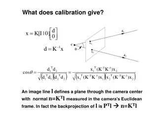
NGAO Calibration/Simulation Source. T. Stalcup, M. Pollard. Requirements. Relay NGS and LGS point sources into AO image plane Wavelength range NGS 500 nm to 2500 n m LGS 589 nm or 594 nm laser line 120 arcsecond field

E N D
NGAO Calibration/Simulation Source T. Stalcup, M. Pollard
Requirements • Relay NGS and LGS point sources into AO image plane • Wavelength range • NGS 500 nm to 2500 nm • LGS 589 nm or 594 nm laser line • 120 arcsecond field • Resolved and unresolved sources at NGS and LGS 85 km and 180 km conjugates • Flat field and spectral line sources • 30 nm rms wavefront error • Estimated specification. Need to produce a calibration budget • Turbulence generator • Optional at summit, decided this shouldn’t drive design • Ground layer at cal unit secondary mirror • 11.5 km conjugate at cal unit primary mirror • More details later in optical design 2
Design Goals • Minimize motion requirements using beam splitters and multiple source points • Include enough focus range for NGS/LGS sources for image sharpening and IF dichroic compensation • Fiber-fed sources to minimize heat and access in AO cold enclosure • Simultaneous operation of NGS/LGS sources • Minimize surfaces • More surfaces requires tighter figure error specification 3
Design Status • Concentrated on difficult part – the optical design • Choice of source sizes, brightness, and wavelengths still in progress • Very flexible design, can put anything in input plane for calibration unit • Flat field source still under development • Optomechanical design in progress 4
Optical Design • Explored a few alternatives – refractive, TMA, etc. • Too complicated or costly due to wavelength range and wavefront quality constraints • Chose an Offner relay • All spherical surfaces • Excellent image quality • Pupil at mirror, not free space 5
250 mm Pupil at secondary mirror Primary mirror Fold down to AO image plane LGS 85 km and 180 km conjugates NGS conjugate NGS/LGS beam splitter Flat field beam splitter Flat Field and spectral line source Optical Design 6
nm rms 30 15 0.5 NGS Performance 8
30 30 18 16 6.5 3.5 LGS Performance nm rms nm rms 90km conjugate 180km conjugate 10
LGS Wavefront Error 90km conjugate 180km conjugate 11
Unresolved Resolved Sources • Point sources are fibers mounted in a fixed plate • Same pattern for NGS and LGS • Mixture of unresolved and resolved sources • Unresolved fiber core is 9 µm, same as current Keck system • Resolved fiber core is 400 µm, or 0.55 arcseconds, also same as current Keck system • Roughly 60 fibers total • Include 589 nm notch filter in NGS to prevent crosstalk 12
NGS Source • Detailed analysis of fiber coupling and throughput pending… • NGS • Tungsten Halogen or Arc Lamp • Some electronic intensity control possible • If electronic dynamic range is insufficient, would need motorized filter wheel • Need electronically controlled shutter for dark images during calibration • Newport Oriel lamp source • RS232 on/off and intensity control • Lamp elapsed hours • Available high stability controller, uses optical feedback to stabilize output 13
LGS Source • DPSS lasers at 589 nm are now available • 10 mW to 2 W output • $4k to $22k • Some electronic intensity control possible • Filter wheel needed if intensity control has insufficient dynamic range • Shutter not needed, can turn on/off electronically • HeNe at 594 nm also an option • Lower power, 2 mW • $2k 14
Flat Field and Spectral Line Source • Uses pupil stop in simulator to define beam • Based on woven fiber optic backlight • Compact, Efficient • Still talking to manufacturer about spectral properties • Use broadband tungsten halogen or arc lamp for flat field • Need to choose spectral lamps – probably hollow cathode type 15
Diffuse lambertian reflector Sources Output plane Alternate Flat Field Source • If woven fiber panels are not suitable • Pattern of several fibers and diffuser • Integrating sphere • Davinci requested uniformity is much less strict than Contour requirements • 10% vs. 0.2% 16
Astrometric Grid • Aluminized glass plate with micromachined 100x100 grid of 3.6 µm holes on 360 µm centers • 5 milliarcseconds diameter, 0.5 arcsecond spacing • Requirement is only for 80x80. Added some for margin at edges when shifting, but if expensive per hole could reduce. • Design very similar to current NIRC2 plate • Backlit with either woven fiber optic or large core fiber with projection optics • On in/out stage with NGS point sources • If flat field arm extended to image plane, could place there • Still need in/out stage • Possible aberrations from flat field beam splitter • Current plan includes a rotation mount for grid • Chosen to keep aberrations from system as constant as possible, but may not be necessary 17
Turbulence Generator • Phase plates near mirrors, two copies of phase distribution separated by ~2-3 mm • Place for 11.5 km phase plate, but it would need to be very large • Wouldn’t fit in AO enclosure with top on • Could be used for warm checkout of tomography 11.5 km conjugate phase plate 250 mm Ground Layer Wheel 18
Elevation Ring Clearance Planar design Increased clearance design 20
Optomechanical • All components mounted to common baseplate except AO rotator fold • Slide in/out of elevation bearing on rails mounted to AO bench • Use overhead crane to lift on/off AO bench • Not sure if commerical mounts will provide wavefront error performance and stability required • Mike Pollard is now past interviews, DAVINCI, etc., and will be filling out design for PDR 21
Questions? 22