Download
1 / 8
80 likes | 169 Vues
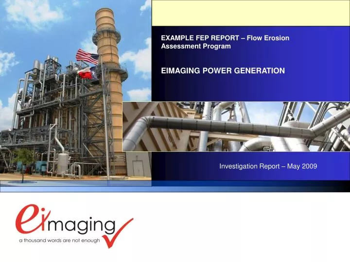
EXAMPLE FEP REPORT – Flow Erosion Assessment Program. EIMAGING POWER GENERATION. Investigation Report – May 2009. PLANT INFORMATION. Last Inspection Date: No Previous Inspections Conducted. Configuration: 2 X 2 X 1 Plant Baseload Capacity: 662 MW Plant Peak Capacity: 692 MW

E N D
EXAMPLE FEP REPORT – Flow Erosion Assessment Program EIMAGING POWER GENERATION Investigation Report – May 2009
PLANT INFORMATION Last Inspection Date: No Previous Inspections Conducted Configuration: 2 X 2 X 1 Plant Baseload Capacity: 662 MW Plant Peak Capacity: 692 MW Plant Construction Date: April 1999 Plant Commercial Operation Date: February 2002 Design Engineer: Construction Contractor: Construction Method: HRSG Supplier: Combustion Turbine Supplier: Steam Turbine Supplier: Pipe Support Supplier: Follow-up Assessment – March 2009 General Manager: Plant Engineer: Operations Manager: Maintenance Manager: Address: 132 Lakeshore Drive, Wheatley, ON N0P 2P0 Tel.: (519) 825-9095
EIMAGING POWER GENERATION EXAMPLE FEP INVESTIGATION REPORT MAY 2009 FEAP – Flow Erosion Assessment Program Flow-Accelerated Corrosion (FAC) Inspections Flow-accelerated corrosion is a function of water chemistry, operating process temperatures, fluid bulk velocities, pipe material and piping geometry. Feedwater pipe operating in the range of 175-deg to 500-deg are susceptible and feedwater systems in range of 200-deg to 350-deg are particularly susceptible. In addition, low-pressure steam piping that operates at or near saturation, or is at risk of two-phase flow, may be exposed to FAC conditions. Click here (slides 99 – 106) for additional program descriptions. The FAC inspection program is designed to be an on-going assessment initiative consisting of evaluating historical data collected from plant records and identifying areas for investigation. In review of the plant’s operating conditions in the boiler feedwater system, a Flow Accelerated Corrosion Inspection program should be initiated and conducted at bi-annual intervals in the areas identified in the following slides: click here(slides 107 thru 129), for FAC program inspection locations.
EIMAGING POWER GENERATION EXAMPLE FEAP INVESTIGATION REPORT MAY 2009 4 FEAP – Flow Erosion Assessment Program EROSION-CORROSION PRINCIPALS IN POWER PIPING • Chemical build-up of protective magnetite [black oxide] (Fe3O4) layer on carbon or low-alloy steel – direct function of dissolved oxygen levels in process flow. • Magnetite layer begins to dissolves into a stream of flowing water (single phase flow) or a water-steam mixture (two phase flow). • The pH-level at temperature and the level of dissolved oxygen in the stream influence the stability and solubility of the magnetite oxide layer. • If the oxidation reduction potential (ORP) is negative, a reducing environment exists that can reduce or eliminate the magnetite protective oxide layer that leads to FAC • Trend to over-treat water with excessive oxygen-scavengers in de-aeration process can accelerate FAC
EIMAGING POWER GENERATION EXAMPLE FEAP INVESTIGATION REPORT MAY 2009 5 FEAP – Flow Erosion Assessment Program GRID TYPE DESIGNATION/ INSPECTION MAPPING ARRANGEMENT FLOW-ACCELERATED CORROSION INSPECTIONS FLOW EROSION ASSESSMENT PROGRAM INSPECTION GRID IDENITFICATION AND ARRANGEMENTS – SHT 1 OF 4
EIMAGING POWER GENERATION EXAMPLE FEAP INVESTIGATION REPORT MAY 2009 6 6 6 FEAP – Flow Erosion Assessment Program GRID TYPE DESIGNATION/ INSPECTION MAPPING ARRANGEMENT NOTES: • Grid width descriptions: the designations in the grid boxes identify number of test points in the pipe circumferential orientation and spacing between points. For instance, 5 @ 1.00” indicates 5 test points spaced 1.00-inches apart • Lengths in the “longitudinal spacing” field identify the spacing of test points. For instance, if the spacing is 1.00”, and the “L” is called out at 8.00”, the number of test points will be nine in the pipe longitudinal direction. • Circumferential grid dimensions are based on total wall mapping of approximately 120-degree on the pipe circumference. The center of the 120-degree arc is identified on the system isometrics. • For grid type “GRD-A2” (elbows), the elongated grid extends along 60-degrees of the elbow sweep and beyond the elbow-weld through “L” inches. Grid type “GRD-A2” may also be specified for upstream end of elbows. FLOW-ACCELERATED CORROSION INSPECTIONS FLOW EROSION ASSESSMENT PROGRAM INSPECTION GRID IDENITFICATION AND ARRANGEMENTS – SHT 3 OF 4
EIMAGING POWER GENERATION EXAMPLE FEAP INVESTIGATION REPORT MAY 2009 7 7 7 7 FEAP – Flow Erosion Assessment Program HRSG 1 Boiler Feedwater Drawing No. M00-00 GENERAL ARRANGEMENT
EIMAGING POWER GENERATION EXAMPLE FEAP INVESTIGATION REPORT MAY 2009 8 8 8 FEAP – Flow Erosion Assessment Program HRSG 1 Boiler Feedwater Drawing No. M-117 Sht. 1 FEEDWATER SUCTION LOCATIONS From LP Drum to Pump A FAC-BFW-101 FAC-BFW-102 FAC-BFW-103 12” NPS Connection PUMP A: 1FW01PA FAC-BFW-104 FAC-BFW-106 FAC-BFW-105