Download

1 / 53
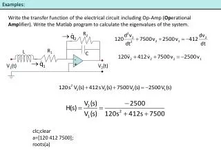
530 likes | 673 Vues
Jarnac examples. Michael Grobe. Topics Introduction: Why simulate? Some reaction kinetics examples Simple production without degradation Production with degradation Bi-directional Multiple species pipeline Negative feedback

E N D
Jarnac examples Michael Grobe
Topics Introduction: Why simulate? Some reaction kinetics examples Simple production without degradation Production with degradation Bi-directional Multiple species pipeline Negative feedback Oscillation produced by negative feedback Positive feedback Coherent, 3-node, positive feed-forward: Low-pass filter Several Jarnac examples were taken from, or inspired by, the Jarnac tutorial presented at ICSB 2007 by Chandra, Kyung, and Sauro
Why simulate? Use simulation to understand the dynamics of reaction pathways, either in part or as a whole. This is a reverse engineering process. You can also use simulation to help forward engineer pathways or organisms (as with synthetic biology). Working with portions of pathways you can investigate “control motifs” that recur in multiple pathways. You can map control motifs to interaction networks like PPI nets to help understand both.
Chemical dynamics are modeled using reaction kinetic equations : For example if A and B are in equilibrium dissociation with AB then : [AB] ----------- = Keq [A] [B] And, if you start with 1000 molecules of A and B, with Keq = 10E-10, then there will be about 730 molecules of AB and 270 each of A and B at equilibrium. For Keq = 10E8, the A/B/AB ratio will be around 915/915/85.
Suppose you have a simple reaction : S ----> P The rate of transition (V) from S to P at any particular moment can be represented as : V = k1 [S] where k1 is an appropriate constant.
Simple Jarnac model of species production without degradation This Jarnac model shows unrestrained production of a species in response to a fixed precursor source concentration ($Source) that is transformed into species S at a rate proportional to the source concentration times the rate constant k1: V1 = k1 * Source .
Simple Jarnac model of species production without degradation // Define the network as a Jarnac object named p p = defn simplemodel // with reaction and rate: $Source -> S; k1 * Source; // V1 end; // end model // initialize kinetic parameters for object p: p.k1 = 1.5; // initialize the starting value for Source p.Source = 2; // run time series: Start at time 0, run for 10 // time units, and collect 100 sets of the data // values for Time, Source and S concentrations. StartTime = 0; StopTime = 10; NumberOfIntervals = 100; m1 = p.sim.eval( StartTime, StopTime, NumberOfIntervals, [ <p.Time>, <p.Source>, <p.S> ]); graph(m1);
Running the Jarnac model Note that the Source concentration remains constant over time.
Here is a run using the same program changed so that the concentration of the precursor, Source, drops as it is converted to S. Removing the “$” in “$Source” allows it’s value to change.
Simple model with degradation This model shows species S created at rate proportional to the Source concentration times the rate constant k1, and simultaneously degraded at a rate proportional to the amount of S times the rate constant k2: V1 = k1 * Source V2 = k2 * S
Simple model with degradation (continued) // define network p = defn cell // with reactions and rates: $Source -> S; k1 * Source; // V1 S -> $Sink; k2 * S; // V2 end; // end model // initialize kinetic parameters p.k1 = 1.5; p.k2 = 1.0; // initialize starting values p.Source = 2; // run time series m1 = p.sim.eval( 0, 10, 100, [ <p.Time>, <p.Source>, <p.S> ]); graph(m1);
If this model reaches an asymptotic value, it will be when ( k1 * Source ) = ( k2 * S ) ( 1.5 * 2 ) = ( 1.0 * S) S = 3.0. Here’s the graph:
If you have a reversible (bi-directional) reaction : S <----> P the rate of transition from S to P at any particular moment will be : V = ( rate of transition from S to P ) – ( rate of transition from P to S ) = k1 [S] – k2 [P] where k1 and k2 are appropriate constants
Simple bi-directional model with degradation Here is a model that shows a species S1 that may reach equilibrium with S2: V1 = k1 * Source V2 = k2 * S1 V3 = k3 * S2 V4 = k4 * S2
Simple bi-directional model with degradation // define network in object p: p = defn cell $Source -> S1; k1 * Source; // produce S1 S1 -> S2; k2 * S1; // produce S2 S2 -> S1; k3 * S2; // S2 returns to S1 S2 -> $Sink; k4 * S2; // S2 is degraded. end; // end object // initialize kinetic parameters: p.k1 = 1.5; p.k2 = 0.8; p.k3 = 1.0; p.k4 = 0.6; // initialize starting values p.Source = 2; // run time series m1 = p.sim.eval( 0, 50, 100, [ <p.Time>, <p.Source>, <p.S1>, <p.S2> ]); graph(m1);
This model should show S1 approaching a horizontal asymptote value where all the paths creating S1 equal all the paths degrading or using S1: ( k1 * Source ) + ( k3 * S2 ) = ( k2 * S1 ) and S2 will reach equilibrium when: ( k2 * S1 ) = ( k3 * S2 ) + ( k4 * S2 ) so that given the current constants: k1 = 1.5; k2 = 0.8; k3 = 1.0; k4 = 0.6;
we can write the simultaneous equations to solve for S1 and S2 at equilibrium: ( k1 * Source ) + ( k3 * S2 ) = ( k2 * S1 ) ( k2 * S1 ) = ( k3 * S2 ) + ( k4 * S2 ) or ( 1.5 * 2 ) + ( 1.0 * S2 ) = ( .8 * S1 ) ( .8 * S1 ) = ( 1.0 * S2 ) + ( .6 * S2 ) the first of which conveniently (in this example) becomes: 3.0 + S2 = .8 * S1 ( 3.0 + S2 ) / .8 = S1 so the second can then be written as ( .8 * ( (3.0 + S2 ) / .8 ) ) = ( 1.0 * S2 ) + ( .6 * S2 ) (3.0 + S2 = 1.6 * S2 3.0 = .6 * S2 S2 = 5 and then S1 = 10.0
Here is a similar example showing a two-species pipeline with no degradation: // define network p = defn cell $Source -> S; k1 * Source; S -> S1; k2 * S; S1 -> $Sink; k3 * S1; end; // end model // initialize kinetic parameters: p.Source = 2; p.k1 = 1.5; p.k2 = 1.0; p.k3 = 0.75; // run time series, and collect values for graph. m1 = p.sim.eval( 0, 10, 100, [ <p.Time>, <p.Source>, <p.S>, <p.S1> ]); graph(m1);
Suppose you have the reaction : S + S ----> P The rate of transition from S to P at any particular moment can be represented as : V = k1 * [S] * [S] where k1 is an appropriate constant. If you have a reaction with 2 different reactants: R + S ----> P the rate of transition from S to P at any particular moment will be : V = k2 * [R] * [S] where k2 is an appropriate constant. These patterns can be generalized to multiple occurrences of multiple species.
Enzyme-mediated reactions: The Michaelis-Menton model If you have an enzyme-mediated reaction such that Enzyme + Substrate goes to EnzymeSubstrate with rate kforward and EnzymeSubstrate returns to Enzyme + Substrate with rate kbackward and EnzymeSubstrate goes irreversibly to Enzyme + Product with rate kcat then you can model this reaction at steady state as [ ES ] = ( kforward / (kbackward + kcat) ) [ E ] [ S ] where the coefficient in parens is the ratio of the rate of conversion to [ES] to the rate of converting back to E and S (kforward) plus the rate of converting forward to P (kcat).
The Michaelis-Menton models of enzyme reactions make further assumptions that simplify the modelling process and derive an ”aggregate ” reaction rate for the conversion of Substrate to Product : Vmax [S] V = ---------- km + [S] where - Vmax is the maximum possible velocity based on having all enzyme bound to substrate, and - the M-M constant, km is kbackward + kcat <- rate of dissociation of ES km = ----------------- kforward + [S] but can be more easily established from measurement than can the other constants(?)
Model of transcription using a Hill function Here is a model of transcription of species S activated by species X, as implemented using a Hill function. V1 = ( Vmax * X ^ h ) / ( K ^ h + X ^ h ) V2 = k1 * S This example was taken from the Jarnac tutorial presented at ICSB 2007 by Chandra, Kyung, and Sauro.
The Hill function and the Hill coefficient The Hill function is used to represent the rate of transcription of a gene (actually the rate of binding of an activator to the promoter region), as a function of the concentration of a activator : Vmax * A^h Rate = ------------ K^h + A^h where - Vmax is the maximum expression level of the promoter, - A is the activator concentration, - h is some integer, typically between 1 and 4, inclusive, and - K, the activation coefficient, is the concentration of A needed to achieve a half-maximal expression rate. And for a repressor, R: Vmax * K^h Rate = ------------ K^h + R^h
Model of transcription (continued) // define network p = defn TranscriptionNetwork $Source -> S; ( Vmax * K^h ) / ( K^h + A^h ); S -> $Sink; k1 * S; end; // end model // initialize kinetic parameters: p.K = 1.0; // Half-maximum rate constant p.Vmax = 7; // Maximum transcription rate p.h = 4; // Hill coefficient p.k1 = 0.3; // run and collect values for graphing with different // concentrations of the activator, A. p.Source = 5; p.A = 1.0; m1 = p.sim.eval( 0, 30, 120, [ <p.Time>, <p.Source>, <p.A>, <p.S> ] );
Model of transcription (continued) p.A = 2.0; m2 = p.sim.eval( 30, 60, 120, [ <p.Time>, <p.Source>, <p.A>, <p.S> ]); p.A = 1.0; m3 = p.sim.eval( 60, 90, 120, [ <p.Time>, <p.Source>, <p.A>, <p.S> ]); p.A = 7.0; m4 = p.sim.eval( 90, 120, 120, [ <p.Time>, <p.Source>, <p.A>, <p.S> ]); // Consolidate and plot results: m = augr( m1, m2 ); m = augr( m, m3 ); m = augr( m, m4); graph(m);
Negative feedback loop example Negative feedback loops are used in pathways to maintain a reliable output signal, not necessarily “constant” since some parameter combinations will yield oscillation. V1 = Source / ( km + S1 ^ h ) V2 = k2 * S V3 = k3 * S1 This example was taken from, or inspired by, the Jarnac tutorial presented at ICSB 2007 by Chandra, Kyung, and Sauro.
Negative feedback loop example (continued) The value of S1 is used to reduce the rate of the first reaction; as S1 grows the rate of the first reaction will diminish, and vice versa. (Note that 4 different Source values are simulated and the results are concatenated.) // define network p = defn NegativeFeedback $Source -> S; Source / ( km + S1^h ); // V1 S -> S1; k2 * S; // V2 S1 -> $Sink; k3 * S1; // V3 end; // end model // initialize kinetic parameters: p.km = 1.0; // Half-maximum rate constant. p.k2 = 1.0; p.k3 = 0.75; p.h = 4; // Hill coefficient // run and collect values for graph with different // values of Source. p.Source = 5.0; m1 = p.sim.eval( 0, 20, 100, [ <p.Time>, <p.Source>, <p.S>, <p.S1> ]);
p.Source = 6.0; m2 = p.sim.eval( 20, 40, 100, [ <p.Time>, <p.Source>, <p.S>, <p.S1> ]); p.Source = 5.0; m3 = p.sim.eval( 40, 60, 100, [ <p.Time>, <p.Source>, <p.S>, <p.S1> ]); p.Source = 5.0; m4 = p.sim.eval( 60, 80, 100, [ <p.Time>, <p.Source>, <p.S>, <p.S1> ]); // Consolidate and plot results: m = augr( m1, m2 ); m = augr( m, m3 ); m = augr( m, m4); graph(m);
In the following graph notice that the level of S1 is only disrupted a small amount by the 20 per cent change in the Source input. Larger changes are also compensated for in a similar fashion.
Negative feedback loop producing oscillation: // define network p = defn Oscillator $Source -> S; Source / ( km + S3^h ); S -> S1; k2 * S; S1 -> S2; k3 * S1; S2 -> S3; k4 * S2; S3 -> $Sink; k5 * S3; end; // end model // initialize kinetic parameters: p.km = 1.0; // Half-maximum rate constant. p.k2 = 1.0; p.k3 = 1.0; p.k4 = 1.0; p.k5 = 1.0; p.h = 6; // Hill coefficient // run and collect values for graph p.Source = 20.0; m = p.sim.eval( 0, 60, 1000, [ <p.Time>, <p.Source>, <p.S>, <p.S1>, <p.S2>, <p.S3> ]); graph(m);
Here are graphs characterizing the oscillation: (from the “Frequency Analysis Module” under the “SBW” tab)
Positive feedback loop producing two possible steady-states: Here the positive feedback rate includes a Hill function on S1, indicating again that the Source ---> S reaction is a transcription step enhanced by feedback from S1. The value of S1 is used to increase the rate of V1; as S1 increases, V1 will also increase (up to a maximum). V1 = Source * ( ( Vmax * S1 ^ h ) / ( km * S1 ^ h ) ) + k1 V2 = k2 * S V3 = k3 * S1 Example program taken from ICSB Tutorial by Chandra, Kyung, and Sauro..
Positive feedback loop with two possible steady-states: // define BistableNetwork p = defn cell $Source -> S; (Vmax * Source * S1^h) / (km + S1^h) + k1; S -> S1; k2 * S; S1 -> $Sink; k3 * S1; end; // end model // initialize kinetic parameters: p.km = 0.1; // Half-maximum rate constant. p.Vmax = 1; p.k2 = 1.0; p.k3 = 0.75; p.h = 4; // Hill coefficient p.k1 = 0.1; p.Source = 1; // Run and collect values for a single graph with // different values of S. p.S = 0.3; m1 = p.sim.eval( 0, 20, 100, [ <p.Time>, <p.Source>, <p.S>, <p.S1> ]); p.S = 0.5;
m2 = p.sim.eval( 20, 40, 100, [ <p.Time>, <p.Source>, <p.S>, <p.S1> ]); p.S = 0.7; m3 = p.sim.eval( 40, 60, 100, [ <p.Time>, <p.Source>, <p.S>, <p.S1> ]); p.S = 0.9; m4 = p.sim.eval( 60, 80, 100, [ <p.Time>, <p.Source>, <p.S>, <p.S1> ]); p.S = 0.3; m5 = p.sim.eval( 80, 100, 100, [ <p.Time>, <p.Source>, <p.S>, <p.S1> ]); p.S = 0.1; m6 = p.sim.eval( 100, 120, 100, [ <p.Time>, <p.Source>, <p.S>, <p.S1> ]); // Consolidate and plot results: m = augr( m1, m2 ); m = augr( m, m3 ); m = augr( m, m4 ); m = augr( m, m5 ); m = augr( m, m6 ); graph(m);
S1 returns to about .14 for perturbations of S = .3 and .5, but once the model is run with S = .7 all subsequent perturbations settle on ~1.4… even runs that originally settled at .14. A “switch” has been flipped.
Example low-pass filter Here is a simple coherent, feed forward network that acts a a low-pass filter. V1 = k1 * ( 2 * ( sin( 10 * Time ) ) ) V2 = k1 * So V3 = k2 * S1 V4 = k3 * So + k4 * So * S1 V5 = k5 * S2 This model should allow low-frequency signals (signals of short duration) to pass more easily than it allows high-frequency signals to pass. This network is derived from the Chandra, Kyung, Sauro tutorial, but modified to send a varying signal into the model. In particular the signal appears as molecular species, So, implemented as a source flow incremented by a sine wave varying from 2 to -2 as a function of Time.
Example low-pass filter // define the model p = defn LowPassFilter $Source -> So; Source + ( 2 * ( sin( N * Time ) ) ); So -> S1; k1 * So; S1 -> $w; k2 * S1; So -> S2; k3 * So + k4 * So * S1; S2 -> $w; k5 * S2; end; //initialize p.Source = 5.0; p.N = 10.0; p.k1 = 1; p.k2 = 1; p.k3 = 1; p.k4 = 1; p.k5 = 1; p.S1 = 0; p.S2 = 0; //Simulate m = p.sim.eval( 0, 50, 1000, [<p.Time>, <p.Source>, <p.So>, <p.S1>, <p.S2> ] ); graph( m );
The following slides show three runs with different values of N in the expression ( N * Time ) which will change the “input” variation frequency over 2 orders of magnitude. As N increases, the magnitude of response of the output species S2 diminishes significantly.
Here is Frequency Analysis output for (all 3 versions of) the model:
A 3-node transcription loop: Here is a coherent 3-node FFL composed of transcription steps. Gene 1 and Gene 3 are both activated by the same activator, Xactivator. The product of Gene1, Protein1, is an activator for expression of Gene 2, and the product of Gene 2, Protein2, activates Gene 3, along with Xactivator.
Code for the the 3-node transcription loop: // define the model p = defn threenodeodeFFL $Vmax -> mRNA1; ( Vmax * ( Xactivator ^ H) ) / ( (km ^ H) + (Xactivator ^ H) ); mRNA1 -> $w; k2 * mRNA1; mRNA1 -> P1; ( Pmax * mRNA1^H ) / ( km^H + mRNA1^H ); P1 -> $w; k3 * P1; $Vmax -> mRNA2; ( Vmax * P1 ^ H ) / ( km ^ H + P1 ^ H ); mRNA2 -> $w; k4 * mRNA2; mRNA2 -> P2; ( Pmax * mRNA2^ H) / ( km^H + mRNA2^H ); P2 -> $w; k5 * P2; $Vmax -> mRNA3; ( Vmax * ( P2^H ) * ( Xactivator^H) ) / ( km ^ H + ( P2^H) * ( Xactivator^H ) ); mRNA3 -> $w; k6 * mRNA3; mRNA3 -> P3; ( Pmax * mRNA3^H ) / ( km^H + mRNA1^H ); P3 -> $w; k7 * P3; Xactivator -> $w; 0.003 * Xactivator; end;
Code for the the 3-node transcription loop (continued): // initialize p.k2 = 1.4; p.k3 = 0.7; p.k4 = 1.2; p.k5 = 0.7; p.k6 = 0.9; p.k7 = 0.7; p.Vmax = 10; p.Pmax = 5; p.H = 4; p.km = 4; // run time series, and collect values for graph with // Xactivator pulses of different duration. The background // Xactivator concentration is 1, with pulses at a // concentration of 6. p.Xactivator = 1.0; m1 = p.sim.eval( 0, 8, 140, [ <p.Time>, <p.Vmax>, <p.Xactivator>, <p.mRNA3>, <p.P3> ] ); p.Xactivator = 6.0; m2 = p.sim.eval( 9, 10, 140, [ <p.Time>, <p.Vmax>, <p.Xactivator>, <p.mRNA3>, <p.P3> ] );