Download
1 / 57
570 likes | 577 Vues
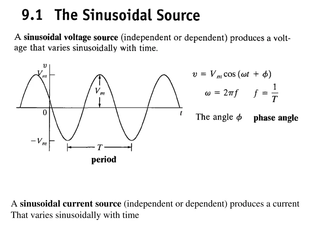
A sinusoidal current source (independent or dependent) produces a current That varies sinusoidally with time. We define the R oot M ean S quare value of v (t) or rms as. The R oot M ean S quare value of. Expand using trigonometric identity. 9.2 The Sinusoidal Response.

E N D
A sinusoidal current source (independent or dependent) produces a current That varies sinusoidally with time
The Root Mean Square value of Expand using trigonometric identity
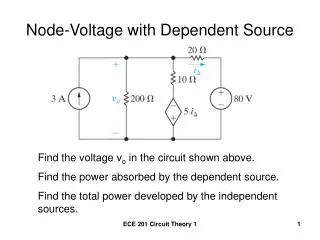
9.2 The Sinusoidal Response On the circuit shown. The source is sinusoidal function and we seek the response in this case is the current i(t) KVL Let assume the solution is Now substituting the solution i (t) into the above differential equation we have Now we seek to find As follows
Solution assumption Equating the terms on the left with the terms on the right , we have Solving
We can summarized the previous method as follows: (2) Substitute the solution assumed in (1) into the differential equation However as the circuit become more complicated ( i.e, more connections of R,L and C ) , the order of the differential equation will increase and the solution using the previous method will not be practical Therefore another technique will be developed as will be shown next
Example Solution for i(t) should be a sinusoidal of frequency 3 We notice that only the amplitude andphasechange In this chapter, we develop a technique for calculating the response directly without solving the differential equation
Time Domain Complex Domain Deferential Equation Complex Algebraic Equation We are going to use complex analysis in the complex domain to do all the algebraic operations ( + , - , X , ÷ ) Therefore we will review complex arithmetic
9.3The phasor The phasor is a complex number that carries the amplitude and phase angle information of a sinusoidal function The phasor concept is rooted in Euler’s identity Euler’s identity relates the complex exponential function to the trigonometric function We can think of the cosine function as the real part of the complex exponential and the sine function as the imaginary part Because we are going to use the cosine function on analyzing the sinusoidal steady-state we can apply
We can move the coefficient Vm inside is a complex number define to be the phasor that carries the amplitude and phase angle of a given sinusoidal function The quantity Phasor Transform Were the notation Is read “ the phasor transform of
Summation Property of Phasor (can be shown)
Since Next we derive y using phsor method
The V-I Relationship for a Resistor Let the current through the resistor be a sinusoidal given as Is also sinusoidal with amplitude And phase The sinusoidal voltage and current in a resistor are in phase
Phasor Transform Phasor Transform Now let us see the pharos domain representation or pharos transform of the current and voltage Which is Ohm’s law on the phasor ( or complex ) domain
The voltage and the current are in phase Imaginary Real
The V-I Relationship for an Inductor Let the current through the resistor be a sinusoidal given as The sinusoidal voltage and current in an inductor are out of phase by 90o The voltage lead the current by 90oor the current lagging the voltage by 90o You can express the voltage leading the current by T/4 or1/4fseconds wereTis the period and fis the frequency
Now we rewrite the sin function as a cosine function ( remember the phasor is defined in terms of a cosine function) The pharos representation or transform of the current and voltage But since Therefore and
and The voltage lead the current by 90oor the current lagging the voltage by 90o Imaginary Real
The V-I Relationship for a Capacitor Let the voltage across the capacitor be a sinusoidal given as The sinusoidal voltage and current in an inductor are out of phase by 90o The voltage lag the current by 90oor the current leading the voltage by 90o
The V-I Relationship for a Capacitor The pharos representation or transform of the voltage andcurrent and
and The voltage lag the current by 90oor the current lead the voltage by 90o Imaginary Real
Phasor ( Complex or Frequency) Domain Time-Domain
Impedance and Reactance The relation between the voltage and current on the phasor domain (complex or frequency) for the three elements R, L, and C we have When we compare the relation between the voltage and current , we note that they are all of form: Which the state that the phasor voltage is some complex constant ( Z ) times the phasor current This resemble ( شبه) Ohm’s law were the complex constant ( Z ) is called “Impedance” (أعاقه ) Recall on Ohm’s law previously defined , the proportionality content R was real and called “Resistant” (مقاومه ) Solving for ( Z ) we have The Impedance of a resistor is In all cases the impedance is measured in Ohm’s W The Impedance of an indictor is The Impedance of a capacitor is
Impedance The Impedance of a resistor is In all cases the impedance is measured in Ohm’s W The Impedance of an indictor is The Impedance of a capacitor is The imaginary part of the impedance is called “reactance” The reactance of a resistor is We note the “reactance” is associated with energy storage elements like the inductor and capacitor The reactance of an inductor is The reactance of a capacitor is Note that the impedance in general (exception is the resistor) is a function of frequency At w = 0 (DC), we have the following short open
Time Domain Phasor (Complex) Domain
9.5 Kirchhoff’s Laws in the Frequency Domain ( Phasor or Complex Domain) Consider the following circuit PhasorTransformation KVL Using Euler Identity we have Which can be written as Factoring Can not be zero Phasor KVL on the phasor domain So in general
Kirchhoff’s Current Law A similar derivation applies to a set of sinusoidal current summing at a node Phasor Transformation KCL KCL on the phasor domain
9.6 Series, Parallel, Simplifications We seek an equivalent impedance between a and b and Ohm’s law in the phosor domain
Example 9.6 for the circuit shown below the source voltage is sinusoidal (a) Construct the frequency-domain (phasor, complex) equivalent circuit ? (b) Calculte the steady state current i(t) ? The source voltage pahsor transformation or equivalent The Impedance of the inductor is The Impedance of the capacitor is
Example 9.7 Combining Impedances in series and in Parallel (a) Construct the frequency-domain (phasor, complex) equivalent circuit ? (b) Find the steady state expressions for v,i1, i2, and i3 ? ? (a)
Delta-to Wye Transformations D to Y Y toD
9.7 Source Transformations and Thevenin-Norton Equivalent Circuits Source Transformations Thevenin-Norton Equivalent Circuits