Download

1 / 57
580 likes | 720 Vues
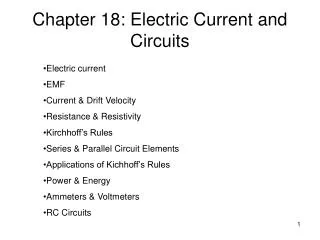
Electric Current and Circuits. HEAT will flow if there is a difference in temperature. WATER will flow if there is a difference in pressure . Is the pressure inside the jug (due to the weight of the water) the same as the pressure outside the jug (due to the weight of the atmosphere)?

E N D
WATER will flow if there is a difference in pressure. Is the pressure inside the jug (due to the weight of the water) the same as the pressure outside the jug (due to the weight of the atmosphere)? If the pressure outside was the same as the pressure inside, would the water flow out? At which location is there a larger difference between the pressure inside and outside, near the top of the water level or near the bottom of the water level? What evidence can you see that demonstrates a larger difference in pressure at the two locations?
Electrons will flow if there is a difference in electric pressure. Electric pressure is called “Potential”, and is measured in Volts. If there is no difference in pressure from one location to another, the electrons will not flow. In other words, if there is no “Potential Difference, DV” from one location to another, there will be no electric “current”.
e- e- e- e- e- e- e- e- Current CURRENT: a flow of charged particles (electrons) through a conductor Current, I, is measured in amperes, A, or “amps”. Andre Ampere
Example: What is the current, I, if 8 C of charge passes through a wire in 2 seconds? I = q / t I = 4 amps
The Damage Caused by Electric Shock 60W light bulb - 0.5 A Starter motor – 210 A Clothes dryer – 18 A Iron- 3 A 1 mA = 0.001 A Mild shock can be felt 5 mA = 0.005 A Shock is painful 15 mA = 0.015 A Muscle control is lost 100 mA = 0.1 A Death can occur
Circuits ELECTRIC CIRCUIT: Charges moving in a closed loop • A circuit requires a both a conductor, usually metal wires, and a “charge pump”. • CHARGE PUMP: a device that provides a potential difference so that charges keep moving. Alessandro Volta The Potential Difference, DV, provided by the charge pump is called its VOLTAGE.
If the voltage of a battery is 1.5 V, this means there is a difference of 1.5 V of potential (pressure) between the positive terminal and the negative terminal. If the voltage of a battery is 9 V, this means there is a difference of 9V of potential (pressure) between the positive terminal and the negative terminal. The pressure DIFFERENCE, the VOLTAGE, is required for charges to flow! So, charge pumps such as batteries, are called voltage sources.
Circuits • This potential difference is sometimes called the emf, e (electromotive force) • Examples of charge pumps: batteries, solar cells, generators, power supplies e
The source of the electrons moving in the circuit is NOT the battery or the wall outlet! The free electrons are contained within the wire itself. An individual electron does not actually travel all the way around a circuit. One electron bumps into the next that bumps into the next that bumps into the next ….. It is the ENERGY that gets transferred all the way around the circuit. You are not buying electrons from your electric company- you already have them! You are buying energy!
Resistance all conductors offer some resistance to the flow of charges, even metal wires. RESISTANCE = The unit for resistance is the OHM, W. This equation is often called OHM’S LAW
Henry Cavendish, who found a value for “G”, also experimented with electricity. His studies laid the groundwork for George Ohm to write Ohm’s Law. George Ohm- first determined the math relationship now called Ohm’s Law
Example What is the resistance of an appliance if 2 amps of current run through it when supplied with 120 V? R = V / I R = 120 V / 2 A R = 60 W
Ohm’s Law As voltage (pressure) changes, the current flowing through a conductor will change. If the ratio of remains constant, that conductor is said to “obey Ohm’s Law”. Example: For one conductor, when Voltage = 12 V, Current = 6 A and when Voltage = 8 V, Current = 4 A. Does it obey Ohm’s Law?
WATER ANALOGY WaterElectricity Flow of watercurrentflow of charge Water pumpkeeps flow goingcharge pump psi.pressurevoltage Pipes of differentresistancewires ofdiameter differentdiameter
Small electrical components called “resistors” are inserted into circuits to control the amount of current flowing.
Certain metals offer less resistance to the flow of charges than others. Example: Copper is a better conductor than iron The resistance of a wire of length L and cross sectional area A is given by RESISTANCE, R = where r is the resistivity of that particular metal.
Schematic diagrams symbols to represent circuit components. wires: Charge pumps: Resistors: Switches: Ground: All devices connected to a circuit (light bulbs, TV’s, toasters, etc.) resist the flow of charges and are sometimes drawn as a resistor in the circuit (if you’re considering the unit as a whole).
SERIES CIRCUITS The same current through each device. EQUIVALENT RESISTANCE: What is the net resistance? What one resistor could replace a group of resistors? For resistors wired in series, the equivalent resistance is given by: Req = R1 + R2 + R3 + …
PARALLEL CIRCUIT Same voltage across each device. For resistors wired in parallel, the equivalent resistance is given by:
Example: What is the equivalent resistance of a 10 W, 20 W, and 30 W resistor wired in series? In parallel? Series: Req = 10 + 20 + 30 = 60 W Parallel 1 / Req = 1/10 + 1/20 + 1/30 Req = 5.45 W There’s much less resistance if resistors are wired in parallel than if they’re wired in series. With less resistance, the charge pump will able to push much more current around the circuit.
For maximum resistance- use series wiring. For minimum resistance- use parallel wiring. The flow of water is a very good analogy to the flow of charges in both series and parallel circuits.
For resistors wired “in series” the same current flows through each one, however the potential difference, voltage, is additive Voltage gain through battery = Sum of Voltage drop through resistors For resistors wired “in parallel”, the potential difference, voltage, is the same for each of them, however the current is additive. Total Current pushed by battery = Sum of Current going through all the resistors
Characteristics of Series and Parallel Wiring Series: If one component goes out, They all go out! As more resistors are added, the equivalent resistance Increases! which means that the current in that part of the circuit Decreases! Parallel: If one component goes out, They rest still work! As more resistors are added, the equivalent resistance Decreases! which means that the current in that part of the circuit Increases!
Electric Power Power is the rate that work is done or energy is transferred, that is Power = Power is measured in Watts, W
Electric power delivered to a circuit by a power supply is given by Power = Current x Voltage P = IV This equation can be combined with Ohm’s Law, R = V / I in its different forms: V = IR, I = V / R
Energy leaves a circuit through the different “resistors” in the form of light, heat, and any kind of work done by the appliance the current is running through. The rate that the energy leaves the circuit is the power output.
Examples How much energy does a 75 W light bulb give off in five minutes? Power = Energy / time Energy = Power x time Energy = 75 W x 5 x 60 seconds Energy = 22500 J What is the power output of a 3 A motor running on regular house voltage? P = IV P = 3 A x 120 V P = 360 W
“Power” lines P =IV • The higher the current, the more the wires in the circuit heat up, thereby “wasting” energy. This is a big problem when electric companies must provide electricity at great distances away from the power plants. • The solution: Electric lines that carry current great distances are at very highvoltage, so the current can be relatively small. P = IV
High Voltage / Low Voltage TRANSFORMERS: devices that “step-up” the voltage at the power plant and then “step-down” the voltage at the customers’ location.
Even with very high voltage, there is still some current running through those wires and power (dissipated through heat) is lost. If the entire length of wire has a total resistance R, the power lost along the way is given by Power lost = I2R
Closed circuit Open circuit
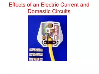
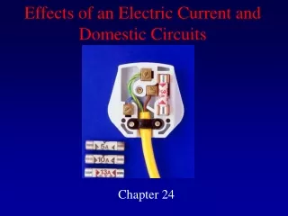
Electrical Safety • Fuse: a short piece of metal that melts if current exceeds a set value (to protect device) • Circuit breaker: an automatic switch that opens the circuit when current exceeds a set value. (uses a bimetallic strip)
Ground-fault circuit interrupter: opens a circuit if the current going into a device is not the same as the current coming out of the device. • gfci
Short Circuit- a circuit that is formed when wires touch. This effectively shortens the path of the circuit because the current no longer passes through the resistor. The extremely low resistance in the circuit produces very high current, which could cause melt down and fire.
Ground wire: provides a path for high current to go in case of a short circuit-