Download
1 / 35
350 likes | 453 Vues
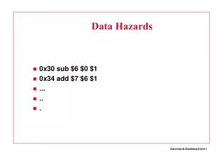
Data Hazards Requiring Stall Cycles. In some code sequence cases, potential data hazards cannot be handled by bypassing. For example: LW R1, 0 (R2) SUB R4, R1, R5 AND R6, R1, R7

E N D
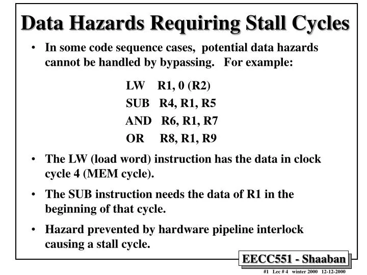
Data Hazards Requiring Stall Cycles • In some code sequence cases, potential data hazards cannot be handled by bypassing. For example: LW R1, 0 (R2) SUB R4, R1, R5 AND R6, R1, R7 OR R8, R1, R9 • The LW (load word) instruction has the data in clock cycle 4 (MEM cycle). • The SUB instruction needs the data of R1 in the beginning of that cycle. • Hazard prevented by hardware pipeline interlock causing a stall cycle.
Hardware Pipeline Interlocks • A hardware pipeline interlock detects a data hazard and stalls the pipeline until the hazard is cleared. • The CPI for the stalled instruction increases by the length of the stall. • For the Previous example, (no stall cycle): LW R1, 0(R1) IF ID EX MEM WB SUB R4,R1,R5 IF ID EX MEM WB AND R6,R1,R7 IF ID EX MEM WB OR R8, R1, R9 IF ID EX MEM WB With Stall Cycle: LW R1, 0(R1) IF ID EX MEM WB SUB R4,R1,R5 IF ID STALL EX MEM WB AND R6,R1,R7 IF STALL ID EX MEM WB OR R8, R1, R9 STALL IF ID EX MEM WB
Compiler Instruction Scheduling for Data Hazard Stall Reduction • Many types of stalls resulting from data hazards are very frequent. For example: A = B + C produces a stall when loading the second data value (B). • Rather than allow the pipeline to stall, the compiler could sometimes schedule the pipeline to avoid stalls. • Compiler pipeline or instruction scheduling involves rearranging the code sequence (instruction reordering) to eliminate the hazard.
a, b, c, d ,e, and f are in memory Stall Stall Compiler Instruction Scheduling Example • For the code sequence: a = b + c d = e - f • Assuming loads have a latency of one clock cycle, the following code or pipeline compiler schedule eliminates stalls: Original code with stalls: LW Rb,b LW Rc,c ADD Ra,Rb,Rc SW a,Ra LW Re,e LW Rf,f SUB Rd,Re,Rf SW d,Rd Scheduled code with no stalls: LW Rb,b LW Rc,c LW Re,e ADD Ra,Rb,Rc LW Rf,f SW a,Ra SUB Rd,Re,Rf SW d,Rd
Control Hazards • When a conditional branch is executed it may change the PC and, without any special measures, leads to stalling the pipeline for a number of cycles until the branch condition is known. • In current DLX pipeline, the conditional branch is resolved in the MEM stage resulting in three stall cycles as shown below: Branch instruction IF ID EX MEM WB Branch successor IF stall stall IF ID EX MEM WB Branch successor + 1 IF ID EX MEM WB Branch successor + 2 IF ID EX MEM Branch successor + 3 IF ID EX Branch successor + 4 IF ID Branch successor + 5 IF Three clock cycles are wasted for every branch for current DLX pipeline
Reducing Branch Stall Cycles Pipeline hardware measures to reduce branch stall cycles: 1- Find out whether a branch is taken earlier in the pipeline. 2- Compute the taken PC earlier in the pipeline. In DLX: • In DLX branch instructions BEQZ, BNEZ, test a register for equality to zero. • This can be completed in the ID cycle by moving the zero test into that cycle. • Both PCs (taken and not taken) must be computed early. • Requires an additional adder because the current ALU is not useable until EX cycle. • This results in just a single cycle stall on branches.
Modified DLX Pipeline: Conditional Branches Completed in ID Stage
Compile-Time Reduction of Branch Penalties • One scheme discussed earlier is to flush or freeze the pipeline by whenever a conditional branch is decoded by holding or deleting any instructions in the pipeline until the branch destination is known (zero pipeline registers, control lines)). • Another method is to predict that the branch is not taken where the state of the machine is not changed until the branch outcome is definitely known. Execution here continues with the next instruction; stall occurs here when the branch is taken. • Another method is to predict that the branch is taken and begin fetching and executing at the target; stall occurs here if the branch is not taken
Static Compiler Branch Prediction Two basic methods exist to statically predict branches at compile time: • By examination of program behavior and the use of information collected from earlier runs of the program. • For example, a program profile may show that most forward branches and backward branches (often forming loops) are taken. The simplest scheme in this case is to just predict the branch as taken. • To predict branches on the basis of branch direction, choosing backward branches as taken and forward branches as not taken.
Profile-Based Compiler Branch Misprediction Rates
Reduction of Branch Penalties:Delayed Branch • When delayed branch is used, the branch is delayed by n cycles, following this execution pattern: conditional branch instruction sequential successor1 sequential successor2 …….. sequential successorn branch target if taken • The sequential successor instruction are said to be in the branch delay slots. These instructions are executed whether or not the branch is taken. • In Practice, all machines that utilize delayed branching have a single instruction delay slot. • The job of the compiler is to make the successor instructions valid and useful instructions.
Delayed Branch-delay Slot Scheduling Strategies The branch-delay slot instruction can be chosen from three cases: • An independent instruction from before the branch: Always improves performance when used. The branch must not depend on the rescheduled instruction. • An instruction from the target of the branch: Improves performance if the branch is taken and may require instruction duplication. This instruction must be safe to execute if the branch is not taken. • An instruction from the fall through instruction stream: Improves performance when the branch is not taken. The instruction must be safe to execute when the branch is taken. The performance and usability of cases B, C is improved by using a canceling or nullifying branch.
(A) (B) (C)
Branch-delay Slot: Canceling Branches • In a canceling branch, a static compiler branch direction prediction is included with the branch-delay slot instruction. • When the branch goes as predicted, the instruction in the branch delay slot is executed normally. • When the branch does not go as predicted the instruction is turned into a no-op. • Canceling branches eliminate the conditions on instruction selection in delay instruction strategies B, C • The effectiveness of this method depends on whether we predict the branch correctly.
Performance of Branch Schemes • The effective pipeline speedup with branch penalties: (assuming an ideal pipeline CPI of 1) Pipeline speedup = Pipeline depth 1 + Pipeline stall cycles from branches Pipeline stall cycles from branches = Branch frequency X branch penalty Pipeline speedup = Pipeline Depth 1 + Branch frequency X Branch penalty
Pipeline Performance Example • Assume the following DLX instruction mix: • What is the resulting CPI for the pipelined DLX with forwarding and branch address calculation in ID stage when using a branch not-taken scheme? • CPI = Ideal CPI + Pipeline stall clock cycles per instruction = 1 + stalls by loads + stalls by branches = 1 + .3 x .25 x 1 + .2 x .45 x 1 = 1 + .075 + .09 = 1.165 Type Frequency Arith/Logic 40% Load 30% of which 25% are followed immediately by an instruction using the loaded value Store 10% branch 20% of which 45% are taken
Branch Penalty Example • For a pipeline similar to the MIPS R4000, it takes three pipeline stages before the branch target address is known and an additional cycle before the branch condition is evaluated. • Assuming no stalls on the registers in the conditional comparison. The branch penalty for the three simplest branch prediction schemes: Branch Scheme Penalty unconditional Penalty untaken Penalty taken Flush pipeline 2.0 3 3 Predict taken 2.0 3 2 Predict untaken 2.0 0 3
Pipelining and Handling of Exceptions • Exceptions are events that usually occur in normal program execution where the normal execution order of the instructions is changed (often called: interrupts, faults). • Types of exceptions include: • I/O device request • Invoking an operating system service • Tracing instruction execution • Breakpoint (programmer-requested interrupt). • Integer overflow or underflow • FP anomaly • Page fault (not in main memory) • Misaligned memory access • Memory protection violation • Undefined instruction • Hardware malfunctions
Exception event IBM 360 VAX Motorola 680x0 Intel 80x86 I/O device request Input/output interruption Device interrupt Exception (Level 0...7 autovector) Vectored interrupt Invoking the operat- ing system service from a user program Supervisor call interruption Exception (change mode supervisor trap) Exception (unimplemented instruction)--- on Macintosh Interrupt (INT instruction) Tracing instruction execution Not applicable Exception (trace fault) Exception (trace) Interrupt (single- step trap) Breakpoint Not applicable Exception (break- point fault) Exception (illegal instruction or break- point) Interrupt (break- point trap) Integer arithmetic overflow or under- flow; FP trap Program interrup- tion (overflow or underflow exception) Exception (integer overflow trap or floating underflow fault) Exception (floating-point coprocessor errors) Interrupt (overflow trap or math unit exception) Page fault (not in main memory) Not applicable (only in 370) Exception (transla- tion not valid fault) Exception (memory- management unit errors) Interrupt (page fault) Misaligned memory accesses Program interrup- tion (specification exception) Not applicable Exception (address error) Not applicable Memory protection violations Program interrup- tion (protection exception) Exception (access control violation fault) Exception (bus error) Interrupt (protection exception) Using undefined instructions Program interrup- tion (operation exception) Exception (opcode privileged/ reserved fault) Exception (illegal instruction or break- point/unimplemented instruction) Interrupt (invalid opcode) Hardware malfunctions Machine-check interruption Exception (machine-check abort) Exception (bus error) Not applicable Power failure Machine-check interruption Urgent interrupt Not applicable Nonmaskable interrupt The names of common exceptions vary across four different architectures.
Characteristics of Exceptions • Synchronous vs. asynchronous: Synchronous: occurs at the same place with the same data and memory allocation Asynchronous: Caused by devices external to the processor and memory. • User requested vs. coerced: User requested: The user task requests the event. Coerced: Caused by some hardware event. • User maskable vs. user nonmaskable: User maskable: Can be disabled by the user task using a mask. • Within vs. between instructions: Whether it prevents instruction completion by happening in the middle of execution. • Resuming vs. terminating: Terminating: The program execution always stops after the event. Resuming: the program continues after the event. The state of the pipeline must be saved to handle this type of exception. The pipeline is restartable in this case.
Handling of Resuming Exceptions • A resuming exception (e.g. a virtual memory page fault) usually requires the intervention of the operating system. • The pipeline must be safely shut down and its state saved for the execution to resume after the exception is handled as follows: • Force a trap instruction into the pipeline on the next IF. • Turn of all writes for the faulting instruction and all instructions in the pipeline. Place zeroes into pipeline latches starting with the instruction that caused the fault to prevent state changes. • The execution handling routine of the operating system saves the PC of the faulting instruction and other state data to be used to return from the exception.
Exception Handling Issues • When using delayed branches ,as many PCs as the the length of the branch delay plus one need to be saved and restored to restore the state of the machine. • After the exception has been handled special instructions are needed to return the machine to the state before the exception occurred (RFE, Return to User code in DLX). • Precise exceptions imply that a pipeline is stopped so the instructions just before the faulting instruction are completed and and those after it can be restarted from scratch. • Machines with arithmetic trap handlers and demand paging must support precise exceptions.
Exceptions in DLX • The following represent problem exceptions for the DLX pipeline stages: IF Page fault on instruction fetch; misaligned memory access; memory-protection violation. ID Undefined or illegal opcode EX Arithmetic exception MEM Page fault on data fetch; misaligned memory access; memory-protection violation WB None • Example: LW IF ID EX MEM WB ADD IF ID EX MEM WB can cause a data page fault and an arithmetic exception at the same time ( LW in MEM and ADD in EX) Handled by dealing with data page fault and then restarting execution, then the second exception will occur but not the first.
Precise Exception Handling in DLX • The instruction pipeline is required to handle exceptions of instruction i before those of instruction i+1 • The hardware posts all exceptions caused by an instruction in a status vector associated with the instruction which is carried along with the instruction as it goes through the pipeline. • Once an exception indication is set in the vector, any control signals that cause a data value write is turned off . • When an instruction enters WB the vector is checked, if any exceptions are posted, they are handled in the order they would be handled in an unpipelined machine. • Any action taken in earlier pipeline stages is invalid but cannot change the state of the machine since writes where disabled.