Download
1 / 6
60 likes | 147 Vues
Strategy for SCRF in next decade. 2007 Develop SCRF Centre of Excellence at TRIUMF industrial (PAVAC) and scientific collaborators (ILC, TTC). Construct γ ,F electron linac. Guarantees, pre-eminence of TRIUMF-ISOL facility for further decade.

E N D
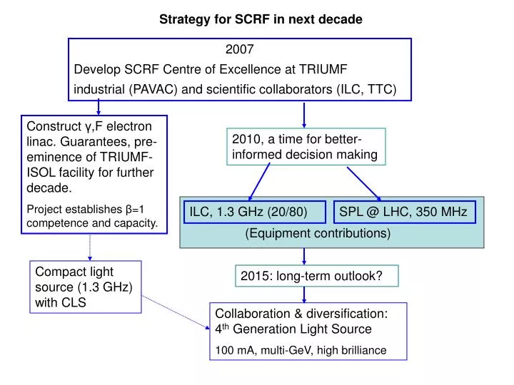
Strategy for SCRF in next decade 2007 Develop SCRF Centre of Excellence at TRIUMF industrial (PAVAC) and scientific collaborators (ILC, TTC) Construct γ,F electron linac. Guarantees, pre-eminence of TRIUMF-ISOL facility for further decade. Project establishes β=1 competence and capacity. 2010, a time for better-informed decision making ILC, 1.3 GHz (20/80) SPL @ LHC, 350 MHz (Equipment contributions) Compact light source (1.3 GHz) with CLS 2015: long-term outlook? Collaboration & diversification: 4th Generation Light Source 100 mA, multi-GeV, high brilliance
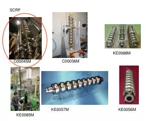
Focus of next two years shall be to master 1.3 GHz SCRF, and to concentrate on those areas that have greatest overlap with ILC: • Single-cell production, 9-cell cavity fabrication, R&D on single-crystal elliptical cavity, process control, etc. • To qualify PAVAC as a N. American supplier. (A major achievement) • Finalize specification of the fission driver during this time – building on accrued expertise. • Infrastructure: build vertical cryostat compatible with 140 MHz and 1.3 GHz cavities; co-opt the 2nd Linde TC50 cryo-system that will be available 2 years in advance of delivery of λ/4 hi-beta cavities; purchase test equipment, etc. • Manpower: additional resources will be required. Combination of machining & e-beam welding (PAVAC) and design, processing (clean room, BCP, HPR), SCRF test equipment and trained expert personnel (TRIUMF) will position us uniquely as a lab with SCRF expertise covering the entire range 0 <β<1.
Nascent SCRF Centre of Excellence positions TRIUMF to: • Build fission driver in 4 yr time frame • Collaborate on spoke cavities for CERN-SOLDE • Collaborate on (β=1) cavities for CLS • TRIUMF/PAVAC to become the major Canadian centre for: ILC (β=1) cavity production and/or for 350 MHz (β<1) cavities for CERN SPL.
Fate of the ERL and IR-FEL addition Fission driver is a high power & beamload, large emittance, long bunch, low HOM loss linac. ERL main linac is converse of that. Nor is there a match to ERL/FEL users requirements: • Very high-current short bunches (ps) with very low emittance (nm) • High-energy electron linac (several GeV) for hard x-ray production. • Conclusion: There is not sufficient overlap of the ERL (& IR-FEL) technical specification with the fission driver to proceed with an ERL addition. • However: CLS interested in Compact Light Source based on “inverse” Compton scattering with requirements: • High-current low-emittance electron gun • Low-energy electron linac: 25 – 250 MeV (i.e. several γ,F modules) • Tera-watt pulsed laser, e.g., TI-Sapphire or CO2. • Could be subject of future collaboration with Canadian Light Source, which could second personnel to TRIUMF for weeks or months to participate in SCRF studies (pending MoU).
Future additions • Vertical cryostat with bath insert for single cavity and nine cell cavity tests • 1.3GHz test area – clean room? • Overhead crane, shielded rf test bunker • Possible area in ISAC-II vault • 2K cryo system • Phase II 500W 4K system will be available from 2007-2009 for cold tests • Require sub-atmospheric pumping system plus recovery/scrubbing system • Outside clean room • 1.3GHz rf test equipment • LLRF control board • Amplifier • Test equipment • Signal generator, freq counter, Power meter, scope, spectrum analyzer • Ancillaries • cables, connectors, mixers, attenuators, phase shifters • Grad students and post-docs from ILC collaboration
Future Possible Light Source - 3 • ICS (“Inverse” Compton Scattering) • Concept: • Use 180º backscatter of laser photons from relativistic electron beam • Use Tera-watt pulsed lasers matched to high-current low-emittance electron bunch • Proof-of-Principle: • Demonstrated at Duke, UCLA, BNL, Frascati, etc. • Under development or construction at MIT, U Tokyo, U Hawaii • Requirements: • High-current low-emittance electron gun • Low-energy electron linac: 25 – 250 MeV • Tera-watt pulsed laser, e.g., TI-Sapphire or CO2 • Pros: • “low” cost – comparable to high-end x-ray beamlines • Competitive for some time-resolved experiments • Possible to tailor design to suit particular types of experiments • Cons: • Least developed concept for x-ray production • Brightness determined by electron beam emittance, hence limited by low beam energy