Download
1 / 26
260 likes | 485 Vues
Single-Cycle CPU DataPath. Building A CPU. We’ve built a small ALU Add, Subtract, SLT, And, Or Could figure out Multiply and Divide. What about the rest How do we deal with memory and registers? What about control operations (branches)? How do we interpret instructions?.

E N D
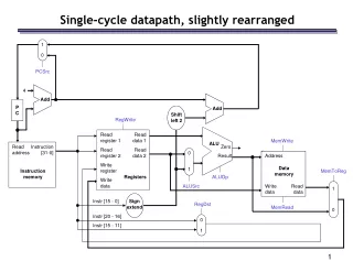
Single-Cycle CPU DataPath
Building A CPU • We’ve built a small ALU • Add, Subtract, SLT, And, Or • Could figure out Multiply and Divide... • What about the rest • How do we deal with memory and registers? • What about control operations (branches)? • How do we interpret instructions? • The whole thing... • A CPU’s datapath deals with moving data around • A CPU’s control manages the data 5.1
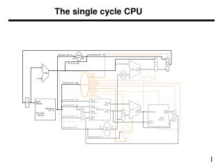
Read reg. num A Read address Read reg data A Data Memory Read reg. num B Read address PC Read data Registers Instruction [31-0] Write address Result Write reg num InstructionMemory Read reg dataB Write data Write reg data ALU Computes on: R-type: 2 registers I-type: Register and data Datapath Overview Current Instruction: PC Instructions: R-type: 3 registers I-type: 2 registers, Data Memory: Address from ALU Data to/from regs Data to write intodest. register from: ALU or Memory 5.1
Add Read address PC Instruction InstructionMemory Instruction Datapath • Instructions will be held in the instruction memory • The instruction to fetch is at the location specified by the PC • Instr. = M[PC] 4 • After we fetch one instruction, the PC must be incremented to the next instruction • All instructions are 4 bytes • PC = PC + 4 Note: Regular instruction width (32 for MIPS) makes this easy 5.2
Instruction Registers R-type Instruction Datapath Read reg. num A Read reg num A Read reg data A Read reg num B Zero Result Write reg num ALU Read reg data B Write reg data • R-type Instructions have three registers • Two read (Rs, Rt) to provide data to the ALU • One write (Rd) to receive data from the ALU • We’ll need to specify the operation to the ALU (later...) • We might be interested if the result of the ALU is zero (later...) 5.2
Data Memory Instruction Zero Registers Result Read reg. num A Read reg num A Read reg data A Read reg num B 16 32 signextend Write reg num Read reg data B Write reg data Memory Operations Read address Read data Write address Write data • Memory operations first need to compute the effective address • LW $t1, 450($s3) # E.A. = 450 + $s3 • Add together one register and 16 bits of immediate data • Immediate data needs to be converted from 16-bit to 32-bit • Memory then performs load or store using destination register 5.2
PC + 4 Result Add Sh.Left2 Registers Read reg. num A Read reg num A Read reg data A Read reg num B Zero Result Write reg num Read reg data B Write reg data 16 32 signextend Branches • Branches conditionally change the next instruction • BEQ $2, $1, 42 • The offset is specified as the number of words to be added to the next instruction (PC+4) Instruction To controllogic • Take offset, multiply by 4 • Shift left two • Add this to PC+4 (from PC logic) offset • Control logic has to decide if the branch is taken • Uses ‘zero’ output of ALU 5.2
Read reg. num A Read reg num A Read address Read reg data A Data Memory Read reg num B Instruction Registers Zero Read data 0 1 Write address Result Write reg num Read reg data B 0 1 Write data Write reg data 16 32 signextend Integrating the R-types and Memory MemoryDatapath • R-types and Load/Stores are similar in many respects • Differences: • 2nd ALU source: R-types use register, I-types use Immediate • Write Data: R-types use ALU result, I-types use memory • Mux the conflicting datapaths together 5.3
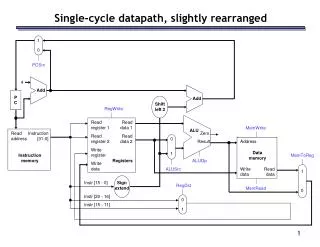
4 Result Registers Add Read reg. num A Read reg num A Read address Read reg data A Data Memory Read reg num B Read address PC Zero Read data 1 Instruction [31-0] Write address Result Write reg num InstructionMemory 0 Read reg data B 0 Write data Write reg data 1 16 32 signextend Adding the instruction memory Simply add the instruction memoryand PC to the beginning of the datapath. Separate Instruction and Data memories are needed in order to allowthe entire datapath to complete its job in a single clock cycle. 5.3
Registers 0 4 Read reg. num A Read reg num A Result 1 Read address Read reg data A Result Data Memory Add Read reg num B Sh.Left2 Add Zero Read data 1 Write address Result Write reg num 0 Read reg data B 0 Write data Write reg data 1 Read address PC Instruction [31-0] InstructionMemory 16 32 signextend Adding the Branch Datapath Now we have the datapath for R-type, I-type, and branch instructions. On to the control logic! 5.3
When does everything happen? 0 4 Result 1 clk Add Result Sh.Left2 Add Single-Cycle Design Read reg. num A Read reg num A Read address Read reg data A Data Memory Read reg num B Read address PC Zero Read data 1 Registers Instruction [31-0] Write address Result Write reg num InstructionMemory 0 0 Read reg data B Write data Write reg data 1 clk clk 16 32 signextend Combinational Logic:Just does it! Outputs are always just a function of its inputs (with some delay) Registers: Written at the end of the clock cycle. (Rising edge triggered). 5.3
Example • Suppose it takes: • memory 100 nsec to read a word, • the ALU and adders take 4 nsec, • the register file can be read or written in 1 nsec, • the PC can be read or written in 0.2 nsec, • all multiplexors take 0.1 nsec. • Assume everything else takes 0 time (control, shift, sign extend, wires, etc.). • How long will it take to execute an add instruction? • How long will it take to execute a lw instruction? • How long will it take to execute a beq instruction? • How long will it take to execute a j instruction?
Registers Read reg. num A Read reg num A Read reg data A Read reg num B Write reg num Read reg data B Write reg data What do we need to control? Mux - are webranching or not? Registers- Should we write data? 0 4 Result 1 Mux - Result fromALU or Memory? Add Result Sh.Left2 Add Read address Data Memory Read address PC Zero Read data 1 Instruction [31-0] Write address Result InstructionMemory 0 0 Write data 1 16 32 signextend Mux - Wheredoes 2nd ALUoperand come from? Memory-Read/Write/neither? ALU -What is theOperation? Almost all of the information we need is in the instruction! 5.3
Operation BInvert CarryIn A 0 1 Result 0 B + 2 1 3 Less CarryOut The ALU • The ALU is stuck right in the middle of everything... • It must: • Add, Subtract, And, or Or for arithmetic instructions • Subtract for a branch on equal • Subtract and set for a SLT • Add for a memory access Function BInvert Op Carryin Result And 0 00 0 R = A • B Or 0 01 0 R = A Ú B Add 0 10 0 R = A + B Subtract 1 10 1 R = A - B SLT 1 11 1 R = 1 if A < B 0 if A ³ B Always the same: Combine into one signal called “sub” 5.3
Setting the ALU controls • The instruction Opcode and Function give us the info we need • For R-type instructions, Opcode is zero, function code determines ALU controls • For I-type instructions, Opcode determines ALU controls New control signal: ALUOp is 00 for memory, 01 for Branch, and 10 for R-type Instruction Opcode ALUOp Funct. Code ALU action ALU control sub op add R-type 10 100000 add 0 10 sub R-type 10 100010 subtract 1 10 and R-type 10 100100 and 0 00 or R-type 10 100101 or 0 01 SLT R-type 10 101010 SLT 1 11 load word LW 00 xxxxxx add 0 10 store word SW 00 xxxxxx add 0 10 branch equal BEQ 01 xxxxxx subtract 1 10 5.3
ALUOp1 F1 A2 ALUOp0 A1 F2 A0 F3 F0 Controlling the ALU For ALUOp = 00 or 01, function code is unused AluOp is determined by Opcode -separate logic will generate ALUOp ALUOp F5 F4 F3 F2 F1 F0 Function ALU Ctrl 00 x x x x x x Add 0 10 x1 x x x x x x Sub 1 10 1x x x 0 0 0 0 Add 0 10 1x x x 0 0 1 0 Sub 1 10 1x x x 0 1 0 0 And 0 00 1x x x 0 1 0 1 Or 0 01 1x x x 1 0 1 0 SLT 1 11 Since ALUOp can only be 00, 01, or 10, we don’t care what ALUOp2 is when ALUOP1 is 1 A 6-input truth table - use standard minimization techniques 5.3
31-26 25-21 20-16 15-11 10-6 5-0 OpcodeRSRTRDShAmtFunction 31-26 25-21 20-16 15-0 OpcodeRSRTImmediate Data Decoding the Instruction - Data The instruction holds the key to all of the data signals R-type To ctrllogic Readreg. A Readreg. B Writereg. To ALUControl Not Used Memory,Branch To ctrllogic Readreg. A Writereg./Readreg. B Memory address or Branch Offset One problem - Write register number must come from two different places. 5.3
Registers Read reg. num A Read reg num A Read reg data A Read reg num B Write reg num Read reg data B 0 Write reg data 1 We can decode the data simply by dividing up the instruction bus Instruction Decoding 0 Opcode: [31-26] 4 Result 1 Add Result Sh.Left2 Add Op:[31-26] Ctrl Rs:[25-21] Read address Rt:[20-16] Data Memory Read address PC Zero Read data 1 Instruction [31-0] Write address Result InstructionMemory 0 0 Write data Rd:[15-11] 1 Read Reg A: Rs Imm:[15-0] 16 32 signextend Read Reg B: Rt Write Reg: Either Rd or Rt Immediate Data: [15-0] 5.3
Registers Read reg. num A Read reg num A Read reg data A Read reg num B Write reg num Read reg data B 0 Write reg data 1 6 Control Signals 0 4 Result 1 Load,R-type BEQ and zero Add Result Sh.Left2 PCSrc Add Op:[31-26] Ctrl MemWrite Load RegWrite Store MemToReg ALUSrc Rs:[25-21] Read address Rt:[20-16] Data Memory Memory Read address PC Zero Read data 1 Instruction [31-0] Write address Result InstructionMemory 0 0 Write data Rd:[15-11] 1 RegDest Imm:[15-0] R-type 00: Memory01: Branch10: R-type ALUCtrl MemRead 16 32 signextend Load FC:[5-0] ALUOp ALU Control - A function of: ALUOp and the function code 5.3
Inside the control oval 00:Mem01:Branch10:R-type 1:Mem0:ALU 0:Reg1:Imm • This control logic can be decoded in several ways: • Random logic, PLA, PAL • Just build hardware that looks for the 4 opcodes • For each opcode, assert the appropriate signals 0:Rt1:Rd 1:Branch Reg ALU Mem Reg Mem Mem Instruction Opcode Write Src To Reg Dest Read Write PCSrc ALUOp R-format 000000 1 0 0 1 0 0 0 10 LW 100011 1 1 1 0 1 0 0 00 SW 101011 0 1 x x 0 1 0 00 BEQ 000100 0 0 x x 0 0 1 01 Note: BEQ must also check the zero output of the ALU... 5.3
We must ANDBEQ and Zero Registers Read reg. num A Read reg num A Read reg data A Read reg num B Write reg num Read reg data B 0 Write reg data 1 6 Control Signals 0 4 Result 1 Add Result Sh.Left2 Add PCSrc BEQ Ctrl MemToReg MemRead MemWrite Op:[31-26] ALUOp ALUSrc RegWrite RegDest Rs:[25-21] Write Read Read address Rt:[20-16] Data Memory Read address PC Zero Read data 1 Instruction [31-0] Write address Result InstructionMemory 0 0 Write data Rd:[15-11] 1 Imm:[15-0] ALUCtrl 16 32 signextend FC:[5-0] 5.3
32 1 28 26 0 4 Registers Read reg. num A Read reg num A Read reg data A Read reg num B Write reg num Read reg data B 0 Write reg data 1 6 Jumping Sh.Left2 Concat. 0 4 Result 1 [31-28] Add Result Sh.Left2 PCSrc Add Jump J:[25-0] BEQ Ctrl MemToReg MemRead MemWrite Op:[31-26] ALUOp ALUSrc RegWrite RegDest Rs:[25-21] Write Read Read address Rt:[20-16] Data Memory Read address PC Zero Read data 1 Instruction [31-0] Write address Result InstructionMemory 0 0 Write data Rd:[15-11] 1 Imm:[15-0] ALUCtrl 16 32 signextend FC:[5-0] 5.3
Performance What major functional units are used by different instructions? R-type: Instr. FetchRegisterReadALURegisterWrite 6ns LW: Instr. FetchRegisterReadALUMemory ReadRegisterWrite 8ns SW: Instr. FetchRegisterReadALUMemory Write 7ns Branch: Instr. FetchRegisterReadALU 5ns Jump: Instr. Fetch 2ns Assume the following times: Since the longest time is 8ns (LW),the cycle time must be at least 8ns. Memory Access: 2ns ALU: 2ns Registers: 1ns
Example • Calculate the execution times for the following program in a Single-cycle datapath with a cycle time of 50 ns main: add $9, $0, $0 # clear $9 lw $8, Tonto($9) # put Tonto[0] in $8 addi $9, $9, 4 # increment $9 lw $10, Tonto($9) # put Tonto[1] in $10 add $11, $10, $8
Example 2 Calculate the execution times for the following program in a Single-cycle datapath with a cycle time of 50 ns • .data • ARRAY: .word 3, 5, 7, 9, 2 #random values • SUM: .word 0 #initialize sum to zero • .text • main: addi $6, $0, 5 #initialize loop counter to 5 • addi $7, $0, 0 #initialize array index to zero • addi $8, $0, 0 #set $8 (sum temp) to zero • REPEAT: lw $5, ARRAY($7) #R5 = ARRAY[i] • add $8, $8, $5 #SUM+= ARRAY[I] • addi $7, $7, 4 #increment index (i++) • addi $6, $6, -1 #decrement loop counter • bne $6, $0, REPEAT #check if 5 repetitions • sw $8, SUM($0) #copy sum to memory • addi $v0, $0, 10 #exit program • syscall