Download
1 / 43
430 likes | 541 Vues
Electron Spin Rotation and Matching Schemes for ELIC, a High Luminosity Ring-Ring Electron-Ion Collider. P. Chevtsov for the ELIC Design Team. SPIN2008, Charlottesville, VA, 6-11 October 2008. Outline. Introduction ELIC Electron Ring Spin Rotation Scheme ELIC Spin Matching Optics Scheme

E N D
Electron Spin Rotation and Matching Schemes for ELIC,a High Luminosity Ring-Ring Electron-Ion Collider P. Chevtsov for the ELIC Design Team SPIN2008, Charlottesville, VA, 6-11 October 2008
Outline • Introduction • ELIC Electron Ring Spin Rotation Scheme • ELIC Spin Matching Optics Scheme • Some ELIC Spin Preparation and Manipulation Issues • Summary
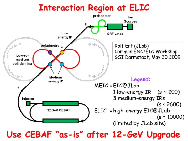
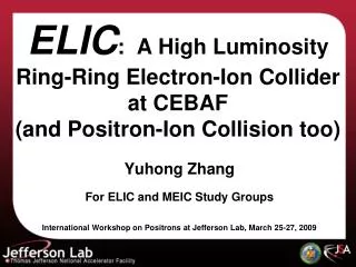
30-225 GeV protons 15-100 GeV/n ions ELIC 12 GeV CEBAF upgrade 3-9 GeV electrons 3-9 GeV positrons ELIC is an Electron-Ion Collider based on CEBAF upgraded to 12 GeV.
30-225 GeV protons 15-100 GeV/n ions ELIC 12 GeV CEBAF upgrade 3-9 GeV electrons 3-9 GeV positrons The CEBAF accelerator with its polarized source will serve as a full energy injector into an electron storage ring providing required beam current, energy, and polarization.
30-225 GeV protons 15-100 GeV/n ions ELIC 12 GeV CEBAF upgrade 3-9 GeV electrons 3-9 GeV positrons Electron and ion storage rings are designed as Figure-8 shaped double rings.
30-225 GeV protons 15-100 GeV/n ions α=0.022 ELIC 12 GeV CEBAF upgrade 3-9 GeV electrons 3-9 GeV positrons Both rings share the same tunnel, with the electron ring above the ion ring. To collide with ions, electrons are bent vertically with a crossing angle of 22 mrad.
ELIC Design Goals • Energy • Center-of-mass energy between 20 GeV and 90 GeV • energy asymmetry of ~ 10, 3 GeV electrons on 30 GeV protons/15 GeV/n ions up to 9 GeV electrons on 225 GeV protons/100 GeV/n ions • Luminosity • 1033 up to 1035 cm-2 s-1per interaction point • Ion Species • Polarized H, D, 3He, possibly Li • Up to heavy ion A = 208, all striped • Polarization • Longitudinal polarization at the IP • Spin-flip of both beams • All polarizations >70% desirable • Polarized Positron Beamdesirable
Electron Polarization in ELIC • Polarized electrons are produced in the CEBAF electron polarized source.
Electron Polarization in ELIC • High polarization of electrons is preserved during their acceleration in CEBAF.
Electron Polarization in ELIC • Polarized beams are injected into the ELIC Figure-8 • shaped ring with vertical polarization.
Spin is vertical in arcs and longitudinal at IPs Electron Polarization in ELIC IP IP IP IP
Electron Polarization in ELIC • Vertical crossing bends cause energy-dependent • spin rotations α=0.022 IP IP IP IP
Electron Polarization in ELIC We need spin rotators that do not change the beam orbit and provide longitudinal spin at IPs at all available electron beam energies (3-9 GeV) α=0.022 IP IP IP IP
Sol1 φ1 Sol2 φ2 α=0.022 B1 B2 α1 α2 SR1
Sol1 φ1 Sol2 φ2 α=0.022 B1 B2 α1 α2 • anomalous magnetic moment of the electron • 0.00115965
Sol1 φ1 Sol2 φ2 α=0.022 B1 B2 α1 α2
Sol1 φ1 Sol2 φ2 α=0.022 B1 B2 α1 α2 B2: γaα2=π/2 at 9 GeV - α2=0.077 B1: α1=2α2
Sol1 φ1 Sol2 φ2 α=0.022 B1 B2 α1 α2 3 GeV – 9 GeV
Sol1 φ1 Sol2 φ2 α=0.022 B1 B2 α1 α2 SR1
SR1 SR2
SR1 SR2
SR1* SR1 SR2
A great effort has been made to ensure the “spin transparency” and spin matching in ELIC.
To avoid depolarization, the optics must be arranged in the way that perturbations caused by the elements in the whole system compensate each other.
electron ring IP IP IP IP - spin tune solenoids - electron spin direction - spin rotators Spin tune solenoids are used to make machine spin tune equal to ½, which compensates most of the spin perturbations.
electron ring IP IP IP IP - spin tune solenoids - electron spin direction - spin rotators The most critical components of the ELIC electron ring are vertical bends and solenoids.
Solenoid (φ – spin rotation) v e- X-Y beam coupling
Decoupling insertion between two solenoids V.Litvinenko, A.Zholents, 1980
quadrupoles v e-
Some ELIC Spin Preparation and Manipulation Issues
12 GeV CEBAF upgrade 3-9 GeV electrons Polarized electrons are available immediately from CEBAF.
12 GeV CEBAF upgrade 3-9 GeV electrons To take the advantage of the Sokolov-Ternov effect, electrons are injected into the ELIC with the direction of polarization that is opposite to the direction of guiding magnetic field.
Transverse Transverse emittance emittance 10 10 MeV MeV filter filter e+ e+ 5 5 MeV MeV Longitudinal Longitudinal emittance filter emittance filter converter converter e e - - polarized polarized source source 15 15 MeV MeV e e - - e e - - e e - - e e - - e+ e+ e+ e+ e+ e+ dipole dipole dipole dipole dipole dipole 115 115 MeV MeV e e - - During positron production: - Polarized source is off - Dipoles are turned on 15 15 MeV MeV unpolarized unpolarized source source Positrons in ELIC • Non-polarized positron bunches are generated from a modified CEBAF electron injector through a converter • Polarization is realized through self-polarization in ring arcs
spin flipping RF dipoles inducing spin resonance frequencies
spin flipping CEBAF
Summary • A concept of spin rotators, which do not change the beam orbit for the ELIC electron ring at all available energies has been developed • Such rotators and spin stabilizing solenoids build up a very efficient spin manipulation system for the ELIC electron ring • The work on spin matching beam transport optics in progress
Electron Polarization in ELIC (cont.) Electron/positron polarization parameters * Time can be shortened using high field wigglers. ** Ideal max equilibrium polarization is 92.4%. Degradation is due to radiation in spin rotators.
the spin precession due to B depends on the beam energy () the spin precession due to B|| is energy-independent • anomalous magnetic moment of the electron • 0.00115965 θsp α The spin precession angle θsp in a dipole magnet with respect to the electron momentum vector is equal to aγα, where α is the dipole bending angle.
Solenoid v e- L spin rotation angle φsp= (1+a) BL/B0ρ BL/B0ρ where B0ρ (T.m) = 3.3356 P (GeV/c)