Download
1 / 40
400 likes | 504 Vues
ELIC G. A. Krafft for the ELIC Study Group EICAC Review Talk Feb 16, 2009. ELIC Study Group & Collaborators.

E N D
ELIC G. A. Krafft for the ELIC Study Group EICAC Review Talk Feb 16, 2009
ELIC Study Group & Collaborators A. Afanasev, A. Bogacz, P. Brindza, A. Bruell, L. Cardman, Y. Chao, S. Chattopadhyay, E. Chudakov, P. Degtiarenko, J. Delayen, Ya. Derbenev, R. Ent, P. Evtushenko, A. Freyberger, D. Gaskell, J. Grames, L. Harwood, A. Hutton, C. Hyde, T. Horn, R. Kazimi, G. A. Krafft, F. Klein, R. Li, L. Merminga, J. Musson, P. Nadel-Turonski, M. Poelker, R. Rimmer, ChaivatTengsirivattana, A. Thomas, H. Wang, C. Weiss, B. Wojtsekhowski, B. Yunn, Y. Zhang - Jefferson Laboratory Staff and Users W. Fischer, C. Montag - Brookhaven National Laboratory V. Danilov - Oak Ridge National Laboratory V. Dudnikov - Brookhaven Technology Group P. Ostroumov - Argonne National Laboratory V. Derenchuk - Indiana University Cyclotron Facility A. Belov - Institute of Nuclear Research, Moscow, Russia V. Shemelin - Cornell University
Topics • Introduction to ELIC: An Electron-Ion Collider Based on CEBAF • Medium Energy Colliders and Staging • R&D Items • Summary
ELIC Design Goals • Energy • Center-of-mass energy between 20 GeV and 100 GeV • Energy asymmetry of ~ 10, 3 GeV electron on 30 GeV proton/15 GeV/n ion up to 10 GeV electron on 250 GeV proton/100 GeV/n ion • Luminosity • >1033 up to 3×1034 cm-2 s-1per interaction point • Ion Species • Polarized H, D, 3He, possibly Li • Up to heavy ion A = 208, fully stripped • Polarization • Longitudinal polarization at the IP for both beams • Transverse polarization of ions • Spin-flip of both beams • All polarizations >70% desirable
Design Choices for ELIC • Use a Ring-Ring (R-R) collider design – take advantage of CEBAF as a full energy polarized electron injector • Energy Recovery Linac – Ring or Circulator Ring - Ring designs have little luminosity advantage and are challenging: high current polarized electron source • ERL-Ring: 2.5 A • Circulator ring: 20 mA • State-of-art: 1.0 mA • 12 GeV CEBAF Upgrade polarized source/injector already meets beam requirement of Ring-Ring design • CEBAF-based R-R design has high luminosity and high polarization
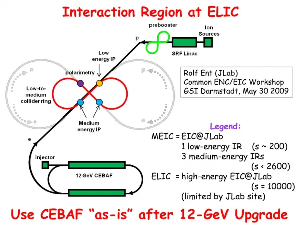
ELIC Conceptual Design Electron Cooling p p Figure-8 collider ring Snake Snake e e e Ion Sources p SRF Linac Electron injector 12 GeV CEBAF
ELIC Ring-Ring Design Features • Unprecedented high luminosity • Enabled by short ion bunches, low β*, high rep. rate • Large synchrotron tune • Require crab crossing • Electron cooling is an essential part of EIC • Four IPs (detectors) for high science productivity • “Figure-8” ion and lepton storage rings • Ensure spin preservation and ease of spin manipulation • No spin sensitivity to energy for all species
Achieving High Luminosity in ELIC ELIC Design Luminosity L~ 3.0 x 1034 cm-2 sec-1 (250 GeV protons x 10 GeV electrons) ELIC Luminosity Concepts • High bunch collision frequency (f=0.5 GHz) • Short ion bunches (σz ~ 5 mm) • Super strong final focusing (β* ~ 5 mm) • Large beam-beam parameters (0.01/0.1 per IP, 0.025/0.1 largest achieved) • Need high energy electron cooling of ion beams • Need crab crossing • Large synchrotron tunes to suppress synchro-betatron resonances • Equidistant phase advance between four IPs
ELIC (p/e) Design Parameters Electron parameters are red
ELIC (A/e) Design Parameters * Luminosity is given per nucleon per IP
IP Magnet Layout and Beam Envelopes 0.5m 3.2kG/cm 0.2m 22.2 mrad 1.27 deg 3.8m 0.6m 2.55kG/cm 8.4cm 10cm IP 1.8m 20.8kG/cm 22.9cm 3m 12KG/cm Vertical intercept Vertical intercept 14.4cm 16.2cm 4.5m Vertical intercept electron 4mm 5mm ion β*OK
IR Final Quad Optimization • IP configuration optimization • “Lambertson”-type final focusing quad • Crab crossing angle 22mrad Electron (10 GeV) 2.4cm 2.4cm 8.6cm 14cm 4.6cm 10 cm 10cm 4.8cm 3cm Proton (250 GeV) 3cm 1.8m 20.8kG/cm 1st SC focusing quad for ion
Lambertson Magnet Design Cross section of quad with beam passing through Magnetic field in cold yoke around electron pass. Paul Brindza
Beam-Beam Effect in ELIC Electron bunch IP Proton bunch Electron bunch proton bunch y x Transverse beam-beam force • Highly nonlinear forces • Produce transverse kicks between colliding bunches • Can cause size/emittance growth or blowup • Can induce coherent beam-beam instabilities • Can decrease luminosity and its lifetime ELIC Case • Highly asymmetric colliding beams (10 GeV/2.5 A on 250 GeV/1 A) • Four IPs and Figure-8 rings • Strong final focusing (β* 5 mm) • Short bunch length (5 mm) • Employs crab cavity • vertical b-b tune shifts are 0.087/0.01 • Very large electron synchrotron tune (0.25) due to strong RF focusing • Equal betatron phase advance (fractional part) between IPs One slice from each of opposite beams Beam-beam force
Beam-Beam Simulations • Simulation Model • Single/multiple IPs, head-on collisions • Strong-strong self consistent Particle-in-Cell codes, developed by J. Qiang of LBNL • Ideal rings for electrons & protons, including radiation damping & quantum excitations for electrons • Scope • 10k ~ 30k turns • 0.05 ~ 0.15 s of stored time (12 damping times) reveals short-time dynamics with accuracy • Simulation results • Equilibrium at 70% of peak luminosity, 1.9×1034 cm-2s-1, the loss is mostly due to the hour-glass effect • Luminosity increase as electron current linearly (up to 6.5 A), coherent instability observed at 7.5 A • Simulations with 4 IPs and 12-bunch/beam showed stable luminosity and bunch sizes after one damping time, saturated luminosity is 1.8×1034cm-2s-1 per IP, very small loss from single IP and single bunch operation Supported by SciDAC 4IPs, 12 bunches/beam
Opportunities for Staging A medium energy EIC becomes the low energy ELIC ion complex Lower energies and symmetric kinematics provide new science opportunities complementary to ELIC/eRHIC: • Valence quarks/gluon structure beyond JLab 12 GeV • Asymmetric sea for x ~ Mπ/ MN • GPDs, transverse spin at x ~ 0.1 Accelerator Advantages/Benefits • Bring ion beams and associated technologies to JLab • Have an early ring-ring collider at JLab • Provides a test bed for new technologies required by ELIC • Develop expertise and experience, acquire/train technical staff
MEIC & Staging of ELIC The tunnel houses 3 rings: Electron ring up to 5 GeV/c Ion ring up to 5 GeV/c Superconducting ion ring for up to 30 GeV/c p p Figure-8 collider ring e e Ion Sources p e SRF Linac Electron injector 12 GeV CEBAF Medium Energy IP Low Energy IP
Medium Energy EIC Features • High luminosity near-symmetric collider • CM energy region up to 24.5 GeV(30x5GeV) • High polarization for both electron and light ion beams • Natural injection path to high energy ELIC • Minimal R&D required • Space charge effect for low ion energy • Beam-Beam effect
MEIC Parameter Table Electron parameters are red
Interaction Region: Simple Optics Mon Dec 01 12:30:09 2008 OptiM - MAIN: - N:\bogacz\Pelican\IR_ion_LR.opt Mon Dec 01 12:26:08 2008 OptiM - MAIN: - N:\bogacz\Pelican\IR_ion_LR.opt 2 2 5 12000 bmax ~ 9 km bmax ~ 9 km Size_X[cm] Size_Y[cm] BETA_X&Y[m] DISP_X&Y[m] b┴* = 5mm b┴* = 5mm s* = 14mm f ~ 7 m f ~ 7 m 0 0 0 0 0 Ax_bet Ay_bet Ax_disp Ay_disp 31.22 0 BETA_X BETA_Y DISP_X DISP_Y 31.22 8 m 8 m • Beta functions • Beam envelopes (σRMS) for εN = 0.2 mm mrad s* = 14mm • Triplet based IR Optics • first FF quad 4 m from the IP • typical quad gradients ~ 12 Tesla/m for 5 GeV/c protons • beam size at FF quads, σRMS ~ 1.6 cm
ELIC Research Plans • Recently submitted to DOE, in conjunction with BNL, for inclusion as “stimulus” funding (15.4 M$ over 5 year grant period) • Items • Common Items • Coherent Electron Cooling (BNL) 8.0 M$ • ERL Technology (JLAB) 8.5 M$ • Polarized 3He Source (BNL) 2.0 M$ • Crab Cavities (JLAB) 2.8 M$ • ELIC Specific Items • Space Charge Effects Evaluation 0.9 M$ • Spin Tracking Including Beam-Beam Force 1.6 M$ • Simulations and Traveling Focus Scheme 1.6 M$
JLAB “Common” Items • Energy Recovery Technology for 100 MeV level electron beam. - Demonstrate beam properties and robust sustainability at high electron current for adevice compatible with circulator cooling ring - Conduct experiments at JLAB FEL Total labor: 20 FTE – years ($ 4.0 M) M&S: $4.5 M Duration: 5 years Subtotal: $8.5M • Crab cavities Issue: The ELIC design is based on the use of crab cavities to reach luminosity at the 1035 cm-2 sec-1 level.Multi-cell crab cavities at 1.5 GHz have not been designed yet, and their effect on the electron and ion beamdynamics needs to be quantified. A. Prototype two 1500 MHz crab cavities B. Develop and test phase and amplitude stability scheme(s). A. Labor: 4 FTE – year ($ 0.8 M) M&S: $200K B. Labor: 4 FTE – year ($ 0.8 M) M&S: $1.0M Subtotal: $2.8M
“ELIC Specific” Items • Ion Space charge simulations (in collaboration with SNS) • Explore “painting” technique for stacking via simulations • Experimental investigation in SNS. A. Total labor: 1.5 FTE – years ($ 0.3 M) Duration: 1 year B. Labor: 0.5 FTE – year ($ 0.1 M) M&S: $500K for diagnostics development Subtotal: $0.9M • Spin Track Studies for ELIC - A. Full electron and ion spin tracking/including vertical bend in electron ring - B. Beam-beam effect on spin depolarization A. Total labor: 2.0 FTE – years ($ 0.4 M) Duration: 2 years B. Labor: 6 FTE – year ($ 1.2 M) Duration: 5 years Subtotal: $1.6M • Studies Traveling Focus Scheme - Feasibility studies for the scheme (essential for ELIC staging) - Develop experimental proof-of-principle program Total labor: 3 FTE – years ($ 0.6 M) Duration: 2 years Subtotal: $0.6M • Simulation studies supporting ELIC project Issue: Use simulations to evaluate electron-ion beam-beam effects, including the kink instability, e-beam disruption and beam emittance growth in the collider. Investigate conventional electron cooling for both magnetized andnon-magnetized schemes. For electron cooling based on a circulator ring, investigate beam cooling interactions and space charge stability of the electron beam in the circulator ring. Total labor:5 FTE-years ($ 1.0 M) Duration: 5 years Subtotal: $1.0M
Summary • The ELIC collider promises to accelerate a wide variety of polarized light ions and unpolarized heavy ions to high energy, enabling a unique physics program. • The final ELIC luminosity should comfortably exceed 1 ×1034 cm-2s-1 for protons. • Low/medium energy stages enable a rich physics program not covered by a high-energy collider. • The initial design studies indicate that luminosity of the intermediate colliders can exceed 1 ×1033 cm-2s-1. This luminosity utilizesstaged ion beam cooling and crab crossing. • The R&D plans supporting ELIC have been recently updated and re-submitted.
ELIC at the JLab Site WM Symantec City of NN VA State 920 m City of NN 360 m SURA JLab/DOE
Production of Ion Beam • One Idea • SRF to 50 to 300 MeV/c • Accumulate current in Low Energy Ring • Accelerate to final energy • Store in Low Energy Ring or send on to next ring • Another Idea • Accelerate to ~ 2 GeV/c in an SRF linac • Accumulate current in Low Energy Ring • Accelerate to final energy • Store in Low Energy Ring or send on to next ring
Circulator Ring Electron Cooling .Effective for heavy ions (higher cooling rate), difficult for protons. • State-of-Art • Fermilab electron cooling demonstration (4.34 MeV, 0.5 A DC) • Feasibility of EC with bunched beams remains to be demonstrated • ELIC Circulator Cooler • 3 A CW electron beam, up to 125 MeV • SRF ERL provides 30 mA CW beam • Circulator cooler for reducing average current from source/ERL • Electron bunches circulate 100 times in a ring while cooling ion beam • Fast (300 ps) kicker operating at 15 MHz rep. rate to inject/eject bunches into/out circulator-cooler ring
Fast Kicker for Circulator Cooling Ring Estimated parameters for the kicker • Sub-ns pulses of 20 kW and 15 MHz are needed to insert/extract individual bunches. • RF chirp techniques hold the best promise of generating ultra-short pulses. State-of-Art pulse systems are able to produce ~2 ns, 11 kW RF pulses at a 12 MHz repetition rate. This is very close to our requirement, and appears to be technically achievable. • Helically-corrugated waveguide (HCW) exhibits dispersive qualities, and serves to further compress the output pulse without excessive loss. Powers ranging from up10 kW have been created with such a device. • Collaborative development plans include studies of HCW, optimization of chirp techniques, and generation of 1-2 kW peak output powers as proof of concept. • Kicker cavity design will be considered kicker kicker
Cooling Time and Ion Equilibrium Cooling rates and equilibrium of proton beam • Multi-stage cooling scenario: • 1st stage: longitudinal cooling at injection energy (after transverses stochastic cooling) • 2nd stage: initial cooling after acceleration to high energy • 3rd stage: continuous cooling in collider mode * max.amplitude ** norm.,rms
Crab Crossing • High repetition rate requires crab crossing to avoid parasitic beam-beam interaction • Crab cavities needed to restore head-on collision & avoid luminosity reduction • Minimizing crossing angle reduces crab cavity challenges & required R&D State-of-art: KEKB Squashed cell@TM110 Mode Crossing angle = 2 x 11 mrad Vkick=1.4 MV, Esp= 21 MV/m
ELIC R&D: Crab Crossing Crab cavity development Electron: 1.2 MV – within state of art (KEK, single Cell, 1.8 MV) Ion: 24 MV (Integrated B field on axis 180G/4m) Crab Crossing R&D program • Understand gradient limit and packing factor • Multi-cell SRF crab cavity design capable for high current operation. • Phase and amplitude stability requirements • Beam dynamics study with crab crossing
Interaction Region: Traveling Focusing slice 1 F1 slice 1 slice 2 sextupole F2 slice 2 • Under same space charge tune-shift limit, we need to increase ion bunch length in order to increase bunch charge, and hence increase luminosity (p < 15 GeV/c) • Hour glass effect would normally kill collider luminosity if ion bunch length is much larger than β* • The “Traveling Focusing” scheme can mitigate hour-glass effect by moving the final focusing point along the long ion bunch. This setup enables the short electron bunch to collide with different slices of the long ion bunch at their relative focusing points • Nonlinear elements (sextupoles) working with linear final focusing block produce non-uniform focus length for different slices of a long bunch Brinkmann and Dohlus, Ya. Derbenev, Proc. EPAC 2002
Electron Polarization in ELIC spin rotator spin rotator spin rotator with 90º solenoid snake collision point collision point collision point collision point spin rotator with 90º solenoid snake spin rotator spin rotator • Produced at electron source • Polarized electron source of CEBAF • Preserved in acceleration at recirculated CEBAF Linac • Injected into Figure-8 ring with vertical polarization • Maintained in the ring • High polarization in the ring by electron self-polarization • SC solenoids at IPs removes spin resonances and energy sensitivity.
Electron polarization parameters * Time can be shortened using high field wigglers. ** Ideal max equilibrium polarization is 92.4%. Degradation is due to radiation in spin rotators.
COSY as Pre-Booster/Collider Ring New superperiod Preserve ring optics • COSY complex provides a good solution for the EIC pre-booster/low energy collider ring • Adding 4 dipoles on each arc can bring maximum momentum of COSY synchrotron from 3.7 GeV/c to 5 GeV/c, while still preserving its optics • COSY existing cooling facilities can be reused