Download
1 / 39
390 likes | 394 Vues
R&D projects on rotating coil probe and stretched wire techniques for CLIC / PACMAN Stephan Russenschuck for the CERN magnet (measurement) -team CLIC workshop 4.02.2014. 1. Rotating Coil Measurements. Tangential coil Radial flux. Radial coil Tangential flux.

E N D
R&D projects on rotating coil probe and stretched wire techniques for CLIC / PACMAN Stephan Russenschuck for the CERN magnet (measurement) -team CLIC workshop 4.02.2014 1
Rotating Coil Measurements Tangential coil Radial flux Radial coil Tangential flux
Standardized Equipment – Motor Drive Unit Drive unit for measurements in horizontal (rt) and vertical (cryogenic temp.) position
Standardized Equipment – Rotating Coil Shafts Shaft R=45 mm, coil length: 130 mm Shaft R=30 mm, coil length: 1200 mm Shaft for measurements in a vertical cryostat
The Riemann Lebesque Lemma The Fourier coefficients tend to zero as n goes to infinity (Riemann Lebesque) and they must scale according to the Cauchy theorem for bounded functions Simulations !
Spread and Noise Floor in Measurements Compensated Blind eye? Noncompensated Radial axes displacement Torsional deformations
Challenges • Sensitivity and tolerances on small shafts • Bucking ratio • Vibrations and noise • Calibration • Connection • PACMAN R&D efforts • PCB technology for coils • Rapid prototyping for shaft • Micro-connectors • MRU-II (smaller, smoother) • In-situ calibration • “Intelligent” post-processing
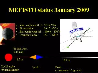
Stretched Wire Experimental Setup Architecture
Wire Excitation Frequencies Measurement system design Map of Second Wire Resonance Stretched wire Oscillating wire Vibrating wire
Solenoid Center and Axis Force distribution requires vibration at the second resonance
Solenoid Center and Axis: Transversal Field Profiles Left: Perfectly aligned. Right: With swing Therefore: Switch to first resonance, and align (move) the magnet, not the stages
Solenoid Center: Oscillation Amplitudes For small displacements from the center, the By component is a linear function in x Modulus At x sensor At y sensor
Map of Second Wire Resonance Solenoid magnet Vibrating wire for magnetic axis Before alignment After alignment
Map of Second Wire Resonance (on 2 mm radius) Solenoid magnet Vibrating wire for magnetic axis
Solving Boundary Value Problems I 1. Governing equation in the air domain 2. Chose a suitable coordinate system, make a guess, look it up in a book, use the method of separation, that is, find orthogonal and completeeigenfunctions. Coefficients are not know at this stage 3. Incorporate a bit of knowledge, rename, and calculate field components
Solving Boundary Value Problems II 4. Measure or calculate the field (flux) on a reference radius and perform a discrete Fourier analysis (develop into the eigenfunctions). Coefficients are known here. 5: Compare the known and unknown coefficients 6. Put this into the original solution for the entire air domain
Solving the Boundary Value Problem Take any 2p periodic function and develop according to For the oscillating wire technique: Use the oscillating amplitudes measured at one position longitudinally as we move the wire such that they become the generators of a cylinder inside the magnet aperture
Response of the Phototransistors Optical sensors Phototransistor Sharp GP1S094HCZ0F
Use Wire Displacements Proposition: We are done if:
Check 2: Numerical simulation (FDTD) and the Steady State Solution
Solution of the Wave Equation III Check: Known longitudinal field or oscillation profiles Ideas welcome on how to measure the longitudinal profile of the oscillation wire (30 phototransistors, inductive, capacitive)
Solution of the Wave Equation IV The slackline The hard-edge (model) magnet
Test Cases Air coil: Academic worst case LEP-IL-QS The “blue” magnet
The Air Coil Longitudinal field distribution Longitudinal shape of the wire oscillation
Conclusion on the Wire Techniques • The classical stretched wire technique is routinely used for axis and gradient measurements • There is still a lot of potential in the oscillating wire technique • Because we measure the oscillation amplitude only at one point, we make in intrinsic error caused by the varying end fields as we move along the circular trajectory • The method is exact for the hard-edge (model) magnet and consequently for small-aperture magnets excited by rare-earth material • There is an intrinsic error because we measure only one amplitude. This error can be estimated when the numerical model is available • Effects from stage misalignment are much larger than the intrinsic error • We would be exact if it was possible to measure the shape of the wire oscillation
Longitudinal field Profiles Behavior around resonance frequencies
Challenges • Bandwidth of the system • Intrinsic error • Noise at 1 kHz • Nonlinearities in the physical model • Tilt and swing alignment of the quadrupole • PACMAN R&D efforts • Measurement of oscillation profiles • New stages and wire tensioning systems • Fiducilization • Software framework (data and task manager) • “Intelligent” postprocessing (tension, multipoles) • String of magnets