Download

1 / 12
190 likes | 618 Vues
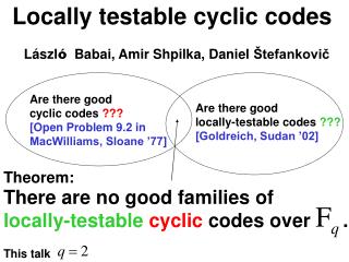
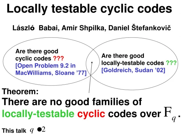
IV. Cyclic Codes. Theorem. Let s(X) be the syndrome of a received polynomial r(X) Then the remainder s (1) (X) resulting from dividing Xs(X) by the generator polynomial g(X) is the syndrome of r (1) (X), which represents a cyclic shift of r(X). Proof Xr(X) = r n-1 (X n +1)+r (1) (X)

E N D
Theorem Let s(X) be the syndrome of a received polynomial r(X) Then the remainder s(1)(X) resulting from dividing Xs(X) by the generator polynomial g(X) is the syndrome of r(1)(X), which represents a cyclic shift of r(X) Proof Xr(X) = rn-1(Xn+1)+r(1)(X) r(1)(X)=rn-1(Xn+1)+Xr(X) Therefore c(X)g(X)+ρ(X) = rn-1g(X)h(X)+X[a(X)g(X)+s(X)] where ρ(X) is the remainder of dividing r(1)(X) by g(X) Therefore Xs(X)=[c(X)+rn-1h(X)+Xa(X)]g(X)+ ρ(X) ρ(X)=s(1)(X) is the remainder of dividing Xs(X) by g(X)
Computing s(1)(X) Gate + + s1 s2 s0 Gate Assume r=(0 0 1 0 1 1 0) The syndrome for r=(0 0 0 1 0 1 1) is s(1)=(1 0 0)
Decoding of Cyclic Codes Cyclic codes may be decoded similar to linear block codes through the following three steps • Syndrome Computation • Association of the syndrome with an error pattern (i.e., syndrome table) • Error Correction Alternatively the cyclic property may be used to simplify the decoding process • Meggitt’s Algorithm • Simplified Syndrome table that stores all correctable error patterns of degree n-1 • Serial Decoding
s’(X) corresponds to a correctable error pattern of degree n-1 Meggitt’s Algorithm r(X)=r0+r1X+r2X2+…+rn-1Xn-1 (received polynomial) r’(X)=r(X), Nof Shifts = 0 Cyclic Shifting r’(X)=r’(1)(X) Compute Syndrome s’(X) for r’(X) Nof Shifts = n Yes No s’(X)=0 No Yes No Yes e’(X)=0 r’(X) is the corrected codeword e’(X)=Xn-1 An error is detected Nof Shifts = Nof Shifts +1, r’(X)=r’(X)+e’(X)
If the syndrome of m(X) is s(X) The syndrome ρ(X) for r’(X)=m(X)+Xn-1 could be computed as follows: m(X)+Xn-1 = a(X)g(X)+ρ(X) ρ(X) = a(X)g(X)+ m(X)+Xn-1 The syndrome ρ(1)(X) for the cyclic shift r’(1)(X) of r’(X)=m(X)+Xn-1 could be computed as follows: Xρ(X)= Xa(X)g(X)+ Xm(X)+Xn Xρ(X)= Xa(X)g(X)+ X[c(X)g(X)+s(X)]+h(X)g(X)+1 Xρ(X)= [Xa(X)+Xc(X)+h(X)]g(X)+Xs(X)+1 Therefore ρ(1)(X)=s(1)(X)+1 where s(1)(X) is the remainder of dividing Xs(X) by g(X) Computing the Syndrome for r’(X)
Cyclic Code Decoder Gate Corrected Vector Received Vector ri + Gate Buffer Register r(X) Feedback Connection Gate Gate + Syndrome Register Error Pattern Detection Circuit ei Gate Syndrome Modification
Meggitt Algorithm Steps Step 1: The syndrome is formed by shifting the entire received vector into the syndrome register. Step 2: The syndrome is read into the detector and is tested for the stored error patterns. The detector is a combinatorial logic circuit that is designed in such a way that its output is 1 if and only if the syndrome in the syndrome register corresponds to a correctable error pattern with an error at the highest order position Xn-1. Step 3: The first received symbol is read out of the buffer. At the same time the syndrome register is shifted once. If the first received symbol is detected to be an erroneous symbol, it is then corrected by the output of the detector. The output of the detector is also fed back to the syndrome register to modify the syndrome (i.e., remove the error effect from the syndrome). This operation results in a new syndrome which corresponds to the altered received vector shifted one place to the right. Step 4: The new syndrome formed in step 3 is used to detect whether the second received symbol (now in the rightmost position) is an erroneous symbol. The detector repeats steps 2 and 3. The second received symbol is corrected in exactly the same manner as the first received symbol was corrected. Step 5: The decoder decodes the received vector symbol by symbol in the manner outlined until the entire received vector is read out of the buffer register
Example Decoding of (7,4) Cyclic Code Syndrome Table g(X)=1+X+X3 • e6(X) is the only error pattern with an error at location X6 • (1 0 1) is the only syndrome that needs to be stored in the • decoder circuit
Example g(X)=1+X+X3:Decoder Circuit Gate Corrected Vector Received Vector Buffer Register ri + Gate r(X) Gate Gate + + Gate
Example g(X)=1+X+X3:Decoder Steps, e(X)=X2 Initial + 0 1st Shift + 0 2nd Shift + 0 3rd Shift + 0 4th Shift + 1 5th Shift + 0 6th Shift + 0 7th Shift + 0
Meggitt’s Algorithm Characteristics • The decoder could be made simpler by storing only the syndromes for error patterns with degree n-1 • The received symbols are serially detected. This introduces a delay in decoding the received vector Meggitt’s Decoder for cyclic codes improves complexity on the expense of increased processing delay Question: Why can’t we adopt the same concept of serial decoding to non-cyclic codes?