Download

1 / 21
1.48k likes | 3.49k Vues
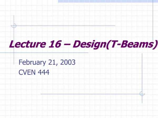
IS 800: 2007 SECTION 12 DESIGN AND DETAILING FOR EARTHQUAKE LOADS. Steel Buildings with no damage after Kobe earthquake. ADVANTAGES OF USING STEEL FOR EARTHQUAKE RESISTANCE. Neither Corrosion nor Cost can be a factor against Steel Structures Steel …

E N D
IS 800: 2007 SECTION 12 DESIGN AND DETAILING FOR EARTHQUAKE LOADS
ADVANTAGES OF USING STEEL FOR EARTHQUAKE RESISTANCE • Neither Corrosion nor Cost can be a factor against Steel Structures • Steel … • is Ductile and gives robust structures • can withstand reversal of stresses • can dissipate considerable energy under cyclic loading • is produced with quality control and suits Capacity Design • gives light and flexible structures – reduction in seismic load • can be easily retrofitted, repaired and rehabilitated with speed
CONTENTS 12. 1 General 12. 2 Load and Load Combinations 12. 3 Response Reduction Factors 12. 4 Connections, Joints and Fasteners 12. 5 Columns and column splice 12. 6 Story drift 12. 7 Ordinary Concentric Braced Frames (OCBF) 12. 8 Special Concentric Braced Frames (SCBF) 12. 9 Eccentrically Braced Frames (EBF) 12.10 Ordinary Moment Frames (OMF) 12.11 Special Moment Frames (SMF) SECTION 12 DESIGN AND DETAILING FOR EARTHQUAKE LOADS
SECTION 12 DESIGN AND DETAILING FOR EARTHQUAKE LOADS 12.1 Scope: Design and Detailing for earthquake resisting frames only 12.2 Load and Load Combinations Earthquake Loads as per IS 1893 – 2002 except for R-factors load combinations for limit state design 1.5 (DL+ LL) 1.2 (DL + LL + EL) 0.9 DL + 1.50EL • Special requirements to avoid instabilities like buckling & over-turning a) 1.2 DL +0.5 LL + 2.5 EL b) 0.9 DL + 2.5 EL (Conti….)
SECTION 12 DESIGN AND DETAILING FOR EARTHQUAKE LOADS 12.3 Response Reduction Factors SI.No Lateral Load Resisting System R 1 Braced frame systems: a)Ordinary Concentrically Braced Frames (OCBF) 4 b) Special Concentrically Braced Frame (SCBF) 4.5 c) Eccentrically Braced Frame (EBF) 5 2 Moment Frame System: a)Ordinary moment frame (OMF) 4 b)Special moment frame (SMF) 5 (Conti….)
CONNECTIONS, JOINTS AND FASTENERS • All bolts used in frames resisting earthquake loads shall be fully tensioned, High Strength Friction Grip (HSFG) bolts, in standard holes. • All welds used in frame resisting earthquake loads shall be complete penetration butt welds, except in column splice • Bolted joints shall not be designed to share load in combination with welds on the same faying surface The black bolts or fillet welds may be used in frames not intended to resist earthquake loads provided they can tolerate the deformation.
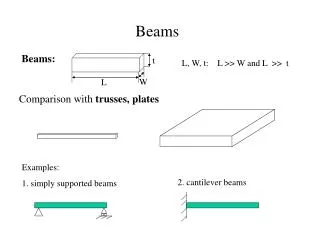
BEAM-TO-COLUMN CONNECTIONS (a) Simple – transfer only shear at nominal eccentricity Used in non-sway frames with bracings etc. Used in frames upto 5 storeys (b) Semi-rigid – model actual behaviour but make analysis difficult (linear springs or Adv.Analysis). However lead to economy in member designs. (c) Rigid – transfer significant end-moments undergoing negligible deformations. Used in sway frames for stability and contribute in resisting lateral loads and help control sway.
column web stiffeners diagonal stiffener web plate (a) (b) (c) Rigid beam-to-column connections a) Short end plate b) Extended end plate c) Haunched BEAM-TO-COLUMN CONNECTIONS
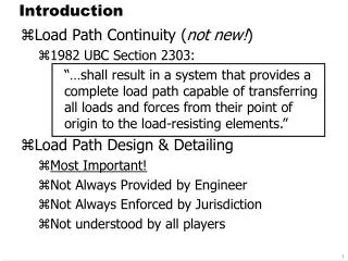
12.5 COLUMNS • Column strength • When Pr/Pc is greater than 0.4….. • Pr is required compressive strength of the member • Pc is actual compressive strength of the member • …… the required axial compressive in the absence of moment to be determined from load combinations • a) 1.2 DL +0.5 LL + 2.5 EL • b) 0.9 DL + 2.5 EL • The required strength determined in above need not exceed • 1.2 times the connecting beam or brace nominal strength • the resistance of the foundation to uplift. • Actual load on column during severe earthquake could be higher due to • system over-strength, frame action, strain hardening & vertical motion
Pmin =0.6 fyAf Pmin =0.6 fyAf COLUMN SPLICE • Partial-joint penetration groove welds, provided in columns splice, shall be designed for 200% of the required strength. STORY DRIFT • The Design Story Drift and story drift limits shall be confirm to IS:1893-2002
Link Beams (a)Diagonal bracing (b)Cross or X-bracing (c )Chevron bracing (d)Eccentric bracing Bracing systems in Steel Frames SEISMIC BEHAVIOUR OF FRAMES Sway frames and non-say frames Braced and un-braced frames Concentrically Braced Frames (CBF) Eccentrically Braced Frames (EBF)
GENERAL COMMENTS ON FRAME CLASSIFICATION • Structural steel frames classified as ordinary and special depending upon their design ductility levels • High seismic zones and important frames, relying more on ductility and use of higher response reduction factors would be beneficial from economic and safety consideration • 12.7.1.1 • Ordinary frames not permitted in seismic zones IV and V • Also in Zone III for structures with I > 1.0
12.7 ORDINARY CONCENTRICALLY BRACED FRAMES (OCBF) • Frame Configuration • Provisions only for diagonal and X- bracing • V and inverted-V to be designed as per specialist literature • K-braced frames not permitted • 12.7.2 Bracing Members • Slenderness of bracing member < 120 • P(required) < 0.8 P(design) • Bracing cross-section not slender (b/t < 15.7 ) • Bracing slopes in both directions • Tensile braces carry 30-70% of load • Built-up braces: local slenderness < 0.4 Overall slenderness • Connection strength to withstand 1.2Agfy, force under additional load combinations and maximum possible force • Check for tension rupture, block shear and gusset local buckling • Connection to withstand 1.2 Mp of brace section
12.8 SPECIAL CONCENTRICALLY BRACED FRAMES (SCBF) • Frame Configuration • Provisions only for diagonal and X- bracing • V and inverted-V to be designed as per specialist literature • K-braced frames not permitted • Bracing Members • Slenderness of bracing member < 160 • P(required) < 1.0 P(actual) • Bracing cross-section plastic (b/t < 9.4 ) • Bracing slopes in both directions • Tensile braces carry 30-70% of load • Built-up braces: local slenderness < 0.4 Overall slenderness • Connection as in OCBF • Columns should have plastic cross-sections • Splices to resist shear and 0.5Mp of smaller section 12.9 Eccentrically Braced Frames (EBF) as per specialist literature
12.10 ORDINARY MOMENT FRAMES (OMF) • Rigid or Semi-rigid moment Connections permitted. • Rigid moment connection to withstand 1.2Mp of beam or the maximum moment that can be delivered, whichever is less. • Semi-rigid connections to withstand 0.5Mp of beam, or the maximum moment that can be delivered, whichever is less . The design moment shall be achieved within a rotation of 0.01 rad. • The stiffness and strength of semi-rigid connection shall be accounted for in the analysis and design, and the overall stability of the frame ensured • Both Rigid and Semi-Rigid connection, to withstand a shear resulting from the load combination 1.5DL+1.5LL plus the shear corresponding to the design moment defined above (respectively). • In Rigid fully welded connections, continuity plates (stiffener plates) of thickness equal to or greater than the thickness of the beam flange shall be provided and welded to the column flanges and web.
12.11 SPECIAL MOMENT FRAMES (SMF) • Beam-to-column joints and connections • Rigid connections only, to withstand a moment of 1.2Mp of beam. • In case of a reduced beam section, 0.8Mp of unreduced section. • The connection to withstand a shear from the load combination 1.2DL+ 0.5LL plus the shear from the application of 1.2 Mp in the opposite sense, at each end of the beam. The shear strength need not exceed the value corresponding to additional load combinations.
cr BUCKLING OF WEBPLATES IN SHEAR Shear buckling of a plate
Continuity plate dp bp Beam-to-column joints and connections (SMF) • In column strong axis connections, the panel zone shall be checked for shear buckling at the design shear defined above. Doubler plates or diagonal stiffener may be used to strengthen the web against shear buckling. The individual thickness of the column webs and doubler plates, shall exceed (dp+bp)/90. • Continuity plates (stiffener plates) shall be provided in all strong axis welded connections except in end plate connection
SPECIAL MOMENT FRAMES (SMF) Beam and column limitation • Beam and column sections shall be plastic or compact. At potential plastic hinge locations, they shall be necessarily plastic. • The section selected for beams and columns shall satisfy the following relation Mpc > 1.2 Mpb • Lateral support to the column at both top and bottom beam flange levels shall be provided so as to resist at least 2% of the beam flange strength, except for the case described below. • A Plane frame with support in the direction perpendicular to its plane, shall be checked for buckling, also under the additional load combination.
12.12 Column Bases • Fixed column bases and anchor bolts to withstand a moment of 1.2 times Mp of column section • All bases to withstand full shear under all load combinations or 1.2 times shear capacity of column section whichever is higher Dr. S. R. Satish Kumar Dept. of Civil Engineering IIT Madras Email: sr.satishkumar@gmail.com THANK YOU