Download
1 / 74
850 likes | 1.25k Vues
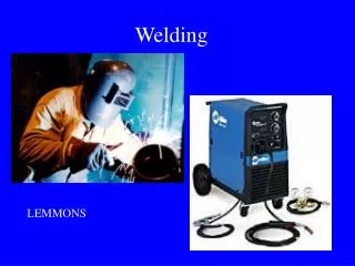
Welding. Welding. Parts are joined together by Fusion. Fusion is brought about by a combination of heat and pressure between parts being joined. In normal welding processes very high temperatures and little or no pressure is used. Welding conditions

E N D
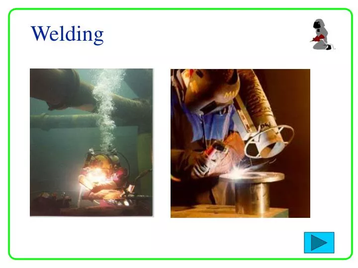
Welding Parts are joined together by Fusion. Fusion is brought about by a combination of heat and pressure between parts being joined. In normal welding processes very high temperatures and little or no pressure is used. • Welding conditions • Smooth joint surfaces that match each other • Surfaces clean and free from oxides, grease and dirt. • Metals to be joined have same microstructure
Welding conditionscontinued…. • The metals should be good quality (no internal impurities) • Welding Preparation • Before starting a weld, the joint edges should be carefully prepared. • Beveling large edges • Cleaning (Chemical/Mechanical) Weld defects Weld Joints Welding Symbols Welding Techniques
Weld Joints - Parts of a Weld Joint • Joint root • Groove face, Root face and Root edge • Root opening and Bevel • Bevel angle, Groove angle and Groove radius Weld Joints - Types of Weld Joint • Butt Joint • Lap Joint • T Joint • Corner joint • Edge Joint • Splice Member
Joint Root is that portion of a joint to be welded where the members are closest to each other • The joint root may be either a point, line, or an area • The joint roots are shown as shaded areas in (A)-(D) and lines in (E) (F)
Groove face, Root face and Root edge • Groove face is “ that surface of a member included in the groove” • Root face (land) is “that portion of the groove face within the joint root” • Root edge is a root face of zero width
Root opening and Bevel • Root opening is the separation between the work pieces at the joint root • Bevel (chamfer) is an angular edge preparation
Butt Joint A joint between two members aligned approximately in the same plane
Lap Joint A joint between two overlapping members
T Joint A joint between two members located approximately at right angles to each other
Corner Joint A joint between two members located at right angles to each other
Edge Joint A joint between the edges of two or more parallel or nearly parallel members
Splice member is “ the work piece that spans the joint in a spliced joint Single-spliced butt joint Double-spliced butt joint with joint filler
Basic components of aWELDING SYMBOL Reference Line (Required element) Arrow Tail Reference Line must always be horizontal, Arrow points to the line or lines on drawing which clearly identify the proposed joint or weld area.
Weld Symbol Terminology OTHER SIDE Work ARROW SIDE Fillet Weld (Arrow Side Only) Fillet Weld (Both sides)
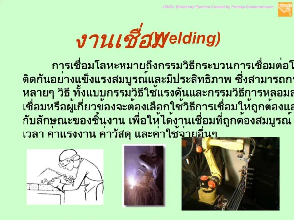
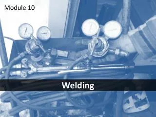
Welding Techniques • There are many different methods of welding. The difference between them is outlined by two important features • The way the metal is heated • The way additional filler metal if any is fed into the weld • Types of Welding • Electric Arc Welding • Gas Welding • Resistance Welding • Friction Welding • Robotic Welding
Electric Arc Welding The heat for fusion is supplied by an electric arc Arc is formed between electrode and work this melts and fuses the joint edges
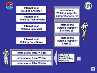
Types of Electric Arc Welding Manual Metal Arc (MMA) Metal Arc Gas Shielded (MAGS) MIG Tungsten Arc Gas Shielded (TAGS) TIG Submerged Arc Welding (SAW)
Manual Metal Arc (MMA) • Most widely used of all the arc welding processes • Commonly called “stick” welding Applications repair work, structural steelwork,
Touch electrode against work withdraw electrode to establish arc. Heat of arc melts base metal, the electrode’s metal core, and any metal particles in electrode’s covering. Heat also melts, vaporises, or breaks down chemically non-metallic substances in covering for arc shielding.Mixing of molten base metal and filler metal from electrode produces coalescence required to effect joining.
Advantages • Used with many electrode types & sizes • Used in all positions • Used on great variety of materials • Flexibility in operator control makes it the most versatile of allweldingprocesses • Low cost of equipment Dis-advantages • Rod becomes shorter & periodically needs replacing • Slows production rate (% time welder welding)
The Electrode and Coating • Coating is a combination of chemicals • Cellulosic electrodes contain cellulose • Rutile electrodes titanium oxide (rutile) • Basic electrodes contain calcium carbonate (limestone) and calcium fluoride (fluorspar)
Function of Electrode Coating • Produce gas to shield weld pool from oxidisising effects of atmosphere • Fluxing elements help weld pool to form • Helps slag to form-removes impurities • Slag slows down cooling preventing Brittleness • Can contain alloying elements or additional filler metal
AC power source Takes power directly from mains power supply. It use a transformer to supply the correct voltage to suit the welding conditions.
DC power source Two types DC generator Transformer-rectifier
DC Generator An electricity generator is driven by a motor. The motor can be electric, petrol or diesel. The generator provides DC current for the arc
Transformer-rectifier A transformer with an electrical device to change AC to DC, this is known as a rectifier. It has the advantage of being able to supply both DC and AC
Basic Transformer-rectifier circuit (AC to DC) Step Down On/Off switch Transformer Bridge Rectifier Smothing Capacitor High AC Voltage 230V + DC output _ Low AC Voltage 10-50V A B C D
A B C D
Transformer A transformer converts AC current at one voltage to AC at a higher or lower voltage Step Down Step Up
Metal Arc Gas Shielded (MAGS)MIG MIG is similar to MMA in that heat for welding is produced by forming an arc between a metal electrode and the workpiece Applications Sheet and Heavy plate, production welding by robots on cars
MIG is similar to MMA in that heat for welding is produced by forming an arc between a metal electrode and the workpiece; the electrode melts to form the weld bead. The main difference is that the metal electrode is a small diameter wire fed from a spool and a sheilding gas is used. As the wire is continuously fed, the process is often referred to as semi-automatic welding.
Advantages • Large gaps filled or bridged easily • Welding can be done in all positions • No slag removal required • High welding speeds • High weld quality • Less distortion of work piece
Equipmnt used in MAGS Three major elements are : Welding torch and accessories Welding control & Wire feed motor Power Source Shielding Gas
Welding torch and accessories GAS DIFFUSER NOZZLE CONTACT TIP • The welding torch guides the wire and shielding gas to the weld zone. • Brings welding power to the wire also • Major components/parts of the torch are the contact tip, shielding gas nozzle, gas diffuser, and the wire conduit
Welding control and wire feed motor • Main function is to pull the wire from the spool and feed it to the arc • Controls wire feed speed and regulates the starting and stopping of wire feed
Welding power source Positive (+) lead is connected to the torch Negative (-) lead is connected to the work piece
Sheilding Gas • Purpose of shielding gas is to protect the weld area from the contaminants in the atmosphere • Gas can be Inert, Reactive, or Mixtures of both • Argon, Helium, and Carbon Dioxide are the main three gases used in MAGS
Tungsten Arc Gas Shielded (TAGS)TIG TIG is similar to MMA in that heat for welding is produced by forming an arc between a metal electrode and the workpiece Applications Used in joining magnesium and Aluminium, stainless steels for high quality welding Thin sheet material
In the TIG process the arc is formed between a pointed tungsten electrode and the workpiece in an inert atmosphere of argon or helium. The small intense arc provided by the pointed electrode is ideal for high quality and precision welding. The electrode is not consumed during welding. Whenfillermetal is required, it must be added separately to theweldpool. There are two currents one for starting the arc the other switched on using a trigger or foot pedal, this is a high frequency current to maintain the arc, this is generated by a separte unit.
Advantages • Superior quality welding • Can be used in mechanised systems • Used to weld aluminium and stainless steels • Free of spatter • Low distortion
Equipment used in TAGS Power source TIG must be operated with a constant current power source - either DC or AC Electrodes Electrodes for DC welding are normally pure tungsten. In AC welding, as the electrode will be operating at a much higher temperature, It should be noted that because of the large amount of heat generated at the electrode, it is difficult to maintain a pointed tip and the end of the electrode assumes a spherical or 'ball' profile.
Sheilding Gas Shielding gas is selected according to the material being welded. • Argon • Argon + Hydrogen • Argon/Helium • Helium is generally added to increase heat input (increase welding speed or weld penetration). Hydrogen will result in cleaner looking welds and also increase heat input, however, Hydrogen may promote porosity or hydrogen cracking.
Submerged Arc Welding (SAW) Similar to MIG welding, SAW involves formation of an arc between a continuously-fed bare wire electrode and the workpiece Applications SAWwelding taking place in the flat position. Ideal for heavy workpieces Carbon-manganese steels,low alloy steelsand stainless steels
Submerged Arc Welding (SAW) The process uses a flux to generate protective gases and slag, and to add alloying elements to the weld pool. A shielding gas is not required. Prior to welding, a thin layer of flux powder is placed on the workpiece surface. The arc moves along the joint line and as it does so, excess flux is recycled via a hopper. Remaining fused slag layers can be easily removed after welding. As the arc is completely covered by the flux layer, heat loss is extremely low. There is no visible arc light, welding is spatter-free and there is no need for fume extraction.