Download
1 / 36

E N D
Welding By Ray F. Straub, CMfgT – Nov. 4th, 2006
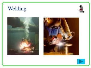
WELDING Welding of metals requires that they be heated to a molten state so that they fuse together. A filler wire or rod is held in the heated zone to add material that will replace metal consumed by the process and to produce a slightly raised area that can be dressed down to make a level surface if needed. Most welding operations today use an electric arc, though the autogenous method using a torch that burns a mixture of (usually) acetylene and oxygen gases to heat the components is still used for certain work. Lasers are also used as the heating medium for some welding operations. In arc welding, a low-voltage, high-current arc is struck between the end of an electrode in a holder and the work, generating intense heat that immediately melts tile surface.
Welding Electrodes, Fluxes, and Processes Electrodes for welding may be made of a tungsten or other alloy that does not melt at welding temperatures (nonconsumable) or of an alloy similar to that of the work so that it melts and acts as the filler wire (consumable). In welding with a nonconsumable electrode, filler metal is added to the pool as welding proceeds. Filler metals that will produce welds having strength properties similar to those of the work are used where high-strength welds are specified. Briefly, the effects of the main alloying elements in welding filler wires and electrodes are: carbon adds strength but may cause brittle weld metal if cooling is rapid, so low-carbon wire is preferred; silicon adds strength and reduces oxidation, changes fluidity, and gives a flatter weld bead; manganese strengthens and assists deoxidation, plus it reduces effects of sulfur, lowering the risk of hot cracking; sulfur may help form iron sulfide, which increases the risk of hot cracking; and phosphorus, may contribute to hot cracking. Fluxes in (usually) granular form are added to the weld zone, as coatings on the filler wire or as a core in the tube that forms the (consumable) electrode. The flux melts and flows in the weld zone, shielding the arc from the oxygen in the atmosphere, and often contains materials that clean impurities from the molten metal and prevent grain growth during recrystallization.
Processes There are approximately 100 welding and allied welding processes but the four manual arc welding processes: gas metal arc welding (GMAW) (which is also commonly known as MIG for metal inert gas), flux-cored arc (FCAW), shielded metal arc (SMAW), gas tungsten arc welding (GTAW), account for over 90 per cent of the arc welding used in production, fabrication, structural, and repair applications. FCAW and SMAW use fluxes to shield the arc and FCAW uses fluxes and gases to protect the weld from oxygen and nitrogen. GMAW and GTAW use mixtures of gases to protect the weld. There are two groups of weld types, groove and fillet, which are self-explanatory. Each type of weld may be made with the work at any angle from horizontal (flat) to inverted (overhead). In a vertical orientation, the electrode tip may move down the groove or fillet (vertical down), or up (vertical up). In any weld other than flat, skill is needed to prevent the molten metal falling from the weld area. Because of the many variables, such as material to be welded and its thickness, equipment, fluxes, gases, electrodes, degree of skill, and strength requirements for the finished welds, it is not practicable to set up a complete list of welding recommendations that would have general validity. Instead, examples embracing a wide range of typical applications, and assuming common practices, are presented here for the most-used welding processes. The recommendations given are intended as a guide to finding the best approach to any welding job, and are to be varied by the user to fit the conditions encountered in the specific welding situation.
Gas Metal Arc Welding (GMAW) The two most cost-effective manual arc welding processes are GMAW and FCAW. These two welding processes are used with more than 50 per cent of the arc welding consumable electrodes purchased. Gas metal arc welding modes extend from short-circuit welding, where the consumable electrode wire is melted into the molten pool in a rapid succession of short circuits during which the arc is extinguished, to pulsed and regular spray transfer, where a stream of fine drops and vaporized weld metal is propelled across the continuous arc gap by electromagnetic forces in the arc. GMAW is the most-used welding process and the two most common GMAW low-carbon steel electrodes used for production welding in North America are the E70S-3 and E70S-6 from the ANSI/AWS Standard A5 series of specifications for arc welding. The E70S-3 contains manganese and silicon as deoxidants and is mainly used for welding low-carbon steels, using argon mixtures as shielding gases. The wire used in the E70S-6 electrodes has more silicon than wire used for the E70S-3 electrodes, and is preferred where straight CO2 or argon mixes are used as the shielding gas or if the metal to be welded is contaminated. The deoxidizing properties of the E70S-6 electrode also may be beneficial for high-current, deep-penetration welds, and welds in which higher than normal impact-strength properties are required. E80S-D2 wire contains more manganese and silicon, plus 0.5 per cent molybdenum for welding such steels as AISI 4130, and steels for high-temperature service. The argon + CO2 mixture is preferred to exert the influence of argon's inertness over the oxidizing action of CO2. E70S-2 electrodes contain aluminum, titanium, and zirconium to provide greater deoxidation action and are valuable for welding contaminated steel plate. When the GMAW welding process is used for galvanized steels, minute welding cracks may be caused by the reaction of the zinc coating on the work with silicon in the electrode. Galvanized steel should be welded with an electrode having the lowest possible silicon content such as the E70S-3. For welding low-carbon and low-alloy steels with conventional argon mixture shielding gases, there is little difference between the E70S-3 and E70S-6. Electrode Diameters.—One of the most important welding decisions is selecting the optimum GMAW electrode diameter. Selection of electrode diameters should be based on the material thickness, as shown for carbon and stainless steels in Table 1, the compatibility of the electrode current requirements with the material thickness, the mode of weld metal transfer, and the deposition rate potential shown in Table 2. The two most popular GMAW electrode sizes are 0.035 in. (1.0 mm) and 0.045 in. (1.2 mm). Diameters of electrodes used for GMAW exert a strong influence on cost of welding. Table 2 also shows how the weld deposition rate varies in short-circuit and spray transfer modes in welding carbon and stainless steels.
GMAW Welding of Sheet Steel In GMAW, the short-circuit transfer mode is used to weld carbon steel, low-alloy steel, and stainless steel sheet of 24 gage (0.023 in., or 0.6 mm) to 11 gage (0.12 in., or 3 mm). The most common gage sizes welded with short-circuit transfer are 20 gage to 11 gage (0.88 to 3 mm) and the best GMAW electrode for these thin, sheet metal gages is the 0.035-in. (1-mm) diameter electrode. The short-circuit current requirements for these operations are typically 50 to 200 amps with voltages in the range of 14 to 22 volts. The optimum short-circuit voltage for the majority of applications is 16 to 18 volts. Shielding Gases for Welding Carbon and Low-Alloy Steels.—With more than 40 GMAW gas mixtures available for welding carbon steels, low-alloy steels, and stainless steels, selection is often confusing. Reactive oxygen and carbon dioxide (CO2) are added to argon to stabilize the arc and add energy to the weld. CO2 can provide more energy to the weld than oxygen. As the CO2 content in a shielding gas mixture is increased to certain levels, the voltage requirements are increased. Argon + oxygen mixtures will require lower voltages than mixtures containing argon with 10 to 25 per cent CO2. Helium may also be added to argon if increased weld energy is required. Shielding Gases for Short-Circuit Welding of Carbon Steels.—GMAW short-circuit transfer (SCT) is used mainly for welding thin metals of less than 10 gage, and gaps. With the SCT mode of weld metal transfer, the arc short circuits many times each second. The numerous short circuits switch the arc energy on and off. The short circuits and low current cause the transferred weld to freeze rapidly. Short-circuit transfer on carbon steel gage metals thicker than 1/16 in. (1.6 mm) requires a shielding gas that will provide substantial weld energy. For these applications, argon with 15-25 per cent CO2 is recommended. If short-circuit transfer is used on metals thinner than 18 gage (0.047 in., 1.2 mm), melt-through and distortion often occur. Melt-through and distortion can be reduced on very thin-gage carbon and low-alloy steels by using a shielding gas that provides less weld energy than argon + 15 to 25 per cent CO2 mixes. Argon + oxygen mixtures can utilize lower voltages to sustain the arc. Argon mixed with 2 to 5 per cent oxygen is a practical mixture for thin carbon steel of less than 16 gage, where there is sensitivity to heat. Shielding Gases for Spray Transfer Welding of Carbon Steels.—With GMAW spray transfer, all traditional argon gas mixtures will provide spatter-free spray weld transfer, depending on the electrode diameter and welding parameters used. The electrode diameter and the electrode current density influence the formation of the weld metal to be transferred. For example, with a 0.035-in. diameter electrode using a mixture containing argon 75 + CO2 25 per cent, a small globular weld droplet is formed on the end of the electrode tip in the conventional spray transfer parameter range. With the same gas mixture, a 0.045-in. (1.2-mm) diameter electrode, and current above 330 amps, the globular formation disappears and the metal transfers in the spray mode. Spatter potential stemming from shielding gas, with 0.035-in. (1.0-mm) and smaller diameter electrodes can be controlled by reducing the CO2 content in the argon mixture to less than 21 per cent. Each different shielding gas will primarily influence the open arc spray transfer mode by variations in the weld energy provided through the welding voltage requirements. Gas selection in spray transfer must be given careful consideration. In welding of clean cold-rolled carbon steel or low-alloy steel less than 3/8 in. (9.5 mm) thick, the energy potential of the arc is less important than it is for welding of steels thicker than 1/4 in. (13 mm) or steels with mill scale. The energy level of the arc is also a key factor in welding steels for which higher than normal impact properties are specified. A simple, practical multipurpose gas mixture for carbon and low-alloy steels is argon + 15 to 20 per cent CO2, and a mixture of argon + 17 per cent CO2 would be ideal. This two-part argon/CO2 mixture provides higher weld energy than two-component argon + CO2 mixtures having less than 10 per cent CO2, argon + oxygen mixtures, or argon + CO2 + oxygen tri-component mixtures. The argon + 17 per cent CO2 mixture will provide an arc slightly less sensitive to mill scale than the other mixtures mentioned. The argon + 17 per cent CO2 mixture also has practical benefits in that it provides sufficient weld energy for all GMAW short-circuit and spray transfer applications with cylinder or bulk gases. The argon + 17 per cent CO2 mixture may also be used for all-position FCAW electrodes in welding carbon steels, low-alloy steels, and stainless steels.
GMAW Welding of Sheet Steel (cont.) Shielding Gases for GMAW Welding of Stainless Steels.—The major problems encountered when using GMAW on stainless steels of thinner than 14 gage include controlling potential melt-through, controlling distortion, and black oxidation on the weld surface. These three welding problems have a common denominator, which is heat. The key to welding thin stainless steel is to minimize the potential heat when welding, by appropriate choice of gas mixture. A popular gas mixture that is often recommended for GMAW welding of thin-gage stainless steel is the three-part helium gas mixture containing helium 90 + argon 7.5 + CO2 2.5 per cent. In contrast to gas mixtures without helium, the helium tri-mixture requires the use of higher voltages to sustain the arc, which adds unnecessary heat to the heat-sensitive thin-gage welds. A practical and lower-cost alternative for GMAW short-circuit transfer on stainless steels is an argon mixture with 2 to 4 per cent CO2. The argon + CO2 mixture allows use of lower voltages than is practical with argon/helium mixtures, and the lower voltages resulting from the argon + CO2 mixture will help to reduce distortion and oxidation, and decrease the melt-through potential. The mixture that works with short-circuit transfer is also a logical practical choice for spray transfer welding of stainless steel because it is less oxidizing than argon/oxygen mixtures. Table 3 provides practical gas mixture recommendations for specific applications. For GMAW spray transfer welding of stainless steels thicker than 11 gage, the traditional GMAW shielding gas has been argon 98 + oxygen 2 per cent. The argon + oxygen mixture provides excellent, stable, spray transfer, but the oxygen promotes oxidation, leaving the weld with a black surface. To reduce the oxidation, the 2 per cent oxygen can be replaced with the less oxidizing 2-4 per cent CO2. Shielding Gases for GMAW Welding of Aluminum.—For GMAW welding of aluminum, helium is added to argon to provide additional weld energy, increasing penetration width, and reducing porosity potential. A gas mixture that has worked well in practice and can be used on the majority of aluminum applications is argon + 25 to 35 per cent helium. Mixtures with higher helium content, of 50 to 90 per cent, require voltages and flow rates that may be excessive for many established aluminum applications. Welding Controls.—The two primary controls for welding with GMAW are the electrode wire feed control on the wire feeder and the voltage control on the power source. As shown in Fig. 1, these controls typically consist of switches and knobs but do not have the scales, seen enlarged at the upper left, that indicate combinations of wire feed rate, wire gage, volts, and amps. These scales have been added here to allow clearer explanation of the functioning of the wire feed control. The typical wire feed unit provides maximum feed rates of 600 to 800 in./min. The scale surrounding the setting knob on a wire feed control unit usually has only 10 unnumbered graduations, somewhat like the hour markers on a clock face. On most machines, each of these graduations represents an adjustment of the feed rate of approximately 70 in./min. For each increase in the wire feed rate of 70 in./min, depending on the voltage, the welding current increases by approximately 20 to 40 amps, depending on the wire diameter and wire feed positions.
Wire Feed Settings for Short-Circuit Welding of Carbon, Low-Alloy, and Stainless Steel Sheet. Many welders set their parameters by an established mark on the equipment or by the sound of the arc as the weld is being made. The sound of the arc, influenced by the optimum current and voltage set, should be a consistent, smooth, crackling noise. If the SCT sound is harsh, the voltage should be increased slightly. If the sound is soft, the voltage should be decreased in volt increments until the sound becomes a smooth crackle. For welding metals thicker than 16 gage but less than 10 gage, the wire feed control should be moved to the eleven o'clock position (280 in./min), and the voltage reset to 18. Welding of thicknesses less than 16 gage should be started with the wire feed control at the nine o'clock position (140 in./min) and the voltage control set to 16. The parameters discussed above apply when using argon mixtures containing 15 to 25 per cent CO2. GMAW Spray Transfer.—In the spray transfer mode, spatter is often caused by the voltage being set so low that the electrode runs into the weld, resulting in expulsion of molten metal from the weld pool. GMAW spray transfer is normally used for welding carbon, low-alloy, and stainless steels of a minimum thickness of 1/8 in. (3.2 mm). Typical deposition rates with a 0.045-in. (1.2-mm) carbon steel electrode are compared with rates for larger carbon steel GMAW and flux-cored electrodes. These welds are typically carried out in the flat and horizontal positions. The practical GMAW electrode diameters commonly used for spray transfer are 0.035-in. (1-mm), 0.045-in. (1.2-mm), and 0.062-in. (1.6-mm) diameter. The most cost-effective GMAW electrode that also has the greatest range of applications on metals over 3/16 in. thick is the 0.045-in. (1.2-mm) diameter size. Typical Deposition Rates for Carbon Steel Welding Electrodes GMAW Spray Transfer Welding of Metal Thicknesses Less than 1/4 in. (6.4 mm).—The most versatile GMAW electrode for a welding shop that welds carbon, low-alloy, and stainless steels from 20 gage to 1/4 in. (6.4 mm) thick is the 0.035-in. (1.0-mm) diameter electrode. The traditional practical spray transfer current range of between 200 and 350 amps for the 0.035-in. electrode is well suited for welding thicknesses from 10 gage to 1/4 in. (6.4 mm). The correct parameters for a 0.035-in. (1-mm) electrode and spray transfer welding are found on the wire feed unit between the one and five o'clock positions, or, on a digital wire feeder, between 420 and 700 in./min. The spray transfer wire feed range is shaded. When the wire feed rate has been set, the voltage should be fine-tuned so that the electrode wire tip is just touching the weld and a smooth crackling sound without spatter is produced. GMAW Spray Transfer Parameters with 0.035-in. (0.9-mm) Diameter Electrodes An optimum single spray transfer mode current setting for a 0.035-in. (1-mm) diameter electrode for most welding applications is approximately 280 amps with the wire feed set at the three o'clock position for 560 in./min. Manual or high-speed mechanized welds on material of 10 gage to 1/4 in. thick can be made at the three o'clock wire feed position with only an adjustment for voltage, which should be set initially at 31 volts, when using an argon + CO2 mixture.
GMAW Spray Transfer for Metal Thicknesses 1/4 in. (6.4 mm) and Up The 0.45-in. (1.2-mm) diameter is the most cost-effective GMAW electrode for spray transfer welding of carbon, low-alloy, and stainless steels 1/4 in. and thicker. A 7/16-in. (11.2-mm) single-pass, no-weave, fillet weld can be produced with this electrode. If larger single-pass welds are required, use of flux-cored electrodes should be considered. A 400-amp power source is a practical cost-effective unit to use with the 0.045-in. diameter electrode. Globular spray transfer, obtained at the ten o'clock position on the wire feed adjustment knob, starts at current levels of approximately 230 amps and requires a wire feed rate of approximately 210 in./min (90 mm/s). Most spray applications are carried out in the higher-energy, deeper-penetrating 270- to 380-amp range, or between twelve and two o'clock wire feed positions giving 350 to 490 in./rain (150 to 210 mm/s). In this range, in which there is minimum weld spatter, the weld deposits are in the form of minute droplets and vaporized weld metal. Some typical settings for feed rate, voltage, and current, with different shielding gases. An ideal starting point with a 0.045-in. (1.2-mm) diameter electrode is to set the wire feed rate knob at the one o'clock position, or 420 in./min, at which rate the current drawn, depending on the power source used, should be about 320 to 350 amps. The best starting voltage for the 0.045-in. (1.2-mm) electrode is 30 volts. With current over 400 amps at 560 in./min, the 0.045-in. diameter electrode may produce a turbulent weld puddle and a digging arc, which can lead to lack of fusion, porosity, and cracks. Some optimum settings for GMAW welding with a mixture of argon + 15 to 20 per cent CO2 gases are given in Table 5. Optimum Settings for GMAW with Argon + 15 20 per cent CO 2 Note: If argon + oxygen gas mixtures are used, voltage should be lowered by 1 to 4 volts for the spray transfer mode. The faster the weld travel speed, the lower the voltage required. Spray Transfer Voltage.—The usual setting for spray transfer welding with commonly used electrode diameters is between 25 and 35 volts (see Fig. 4A). To set the optimum voltage for GMAW spray transfer, set the voltage initially so that it is too high, usually between 30 and 35 volts. With excess voltage, there should be a visible gap between the tip of the electrode and the weld, and the arc sound should be free from crackle. The voltage should now be reduced until a consistent smooth crackle sound is produced. If the voltage is lowered too much, the electrode will run into the weld, making a harsh crackling sound, and the resulting weld expulsion will cause spatter.a
Gas Tungsten Arc Welding Often called TIG (for tungsten inert gas) welding, gas tungsten arc welding (GTAW) uses a nonconsumable tungsten electrode with a gas shield, and was, until the development of plasma arc welding (PAW), the most versatile of all common manual welding processes. Plasma arc welding is a modified GTAW process. In contrast to GTAW, plasma arc welding has less sensitivity to arc length variations, superior low-current arc stability, greater potential tungsten life, and the capability for single-pass, full-penetration welds on thick sections. In examining a potential welding application, the three primary considerations are: achieving a quality weld, ease of welding, and cost. Selecting the optimum weld process becomes more complex as sophisticated electronic technology is applied to conventional welding equipment and consumable electrodes. Rapid advances in gas metal arc and PAW welding power source technology, and the development of many new flux-cored electrodes, have made selection of the optimum welding process or weld consumable more difficult. When several manual welding processes are available, the logical approach in considering GTAW for production welding is to first examine whether the job can be welded by gas metal arc or flux-cored methods. GTAW Welding Current.—A major benefit offered by GTAW, compared with GMAW, FCAW, or SMAW, is the highly concentrated, spatter-free, inert heat from the tungsten arc, which is beneficial for many applications. The GTAW process can use any of three types of welding current, including: direct-current straight polarity, electrode negative (DC-), direct-current reverse polarity, electrode positive (DC+), alternating current with high frequency for arc stabilization (ACHF). Each of the different current types provides benefits that can be used for a specific application.
GTAW Direct-Current Straight Polarity (DC-) The most common GTAW current is straight polarity, where the electrode is connected to the negative terminal on the power source and the ground is connected to the positive terminal. Gas tungsten arc welding is used with inert gases such as argon, and argon + helium to weld most metals. During a DC- straight-polarity weld, electrons flow from the negative tungsten electrode tip and pass through the electric field in the arc plasma to the positive workpiece. Plasma is a high-temperature, ionized, gaseous column that is formed when electrons in the arc collide with the shielding gas molecules. The gas atoms lose one or more electrons, leaving them positively charged. The electrons and the resulting plasma are concentrated at the electrode tip, where they cause the plasma pressure to be at its greatest. The electron density thins out as the electrons travel from the straight-polarity, negatively charged, tungsten electrode across the open arc. As the electrons traverse the arc to the work, the resulting arc column width increases slightly, controlled in part by the electromagnetic forces generated by the current. With the increase in the arc column width, the density and pressure of the plasma decrease. The electrons collide with the work, liberating much heat. The downward pressure of the plasma is exerted against the surface of the weld pool. The gas ions in the plasma are positively charged and greater in mass than the electrons. In DC-, straight-polarity welding, the positive gas ions are drawn to the negative electrode. The electron flow to the weld ensures that most of the arc heat is generated at the positive work side of the arc. This current setup provides maximum penetration potential. With DC-, straight polarity, the tungsten electrode can carry a higher current and operate at lower temperatures than with the other current arrangements. Direct-Current Reverse Polarity (DC+): With direct-current positive polarity (DC+), the tungsten electrode is connected to the power-source positive terminal so that the electrons flow from the negative work to the positive electrode. The electrons impinging on the electrode tip reverse the direction of the heat concentration that occurs with straight polarity, as described above. Approximately two-thirds of the heat generated with DC+ reverse polarity is at the electrode tip, and the electrode becomes very hot, even with low current levels. DC+ reverse polarity requires large-diameter electrodes.
Straight Polarity (DC-) Provides Highest Electrode Current Capacity and Deepest Penetration Potential. In the current range of 100 to 150 amps, DC+ reverse polarity requires a 1/4-in. (6.4-mm) diameter electrode. This larger electrode produces a weld puddle almost twice as wide as that produced by a 120-amp, 1/16-in. (1.6-mm) diameter, DC- straight polarity electrode. Most of the heat is generated at the electrode tip with DC+ reverse polarity, so penetration is much less than with DC- straight polarity. With DC+ reverse polarity, the positive gas ions in the arc plasma are drawn to the negative workpiece where they bombard and break up the surface oxides that form on metals such as aluminum and magnesium. However, the best welding method for aluminum and magnesium is to use alternating current (AC), which combines the benefits of DC- straight and DC+ reverse polarity. Alternating Current (AC): The surface oxides formed on metals such as aluminum and magnesium disturb the arc and reduce the weld quality. Welding of these metals requires DC+ reverse or AC polarity to break up the surface oxides. An alternating current (AC) cycle consists of one-half cycle of straight polarity and one-half cycle of reverse polarity. With alternating current, the cleaning action benefits of the reverse-polarity arc can be combined with the electrode current-carrying capacity of the straight-polarity arc. In welding aluminum and magnesium, the half cycles of AC polarity may become unbalanced. During the AC cycle, the reverse electrode-positive portion of the cycle is restricted by the oxides on the surfaces of these materials. The surface oxides are poor conductors and make it difficult for the electrons generated by the reverse-polarity part of the cycle to flow from the work to the electrode tip, but they do not upset the straight polarity in which the electrons flow from the electrode to the work. Direct-Current (DC+) Reverse Polarity Provides a Shallow, Wide, Weld Pool. DC Component: The part of the reverse-polarity cycle of alternating current (AC) that is upset by the poor conductivity of the oxides is changed into direct-current, straight polarity (DC-) and is directed back to the power source where it may cause overheating. The feedback is referred to as the DC component and its characteristics are important in deciding which process to use because, if an AC power source designed for shielded metal arc welding is to be used to weld aluminum by the GTAW process, the power source must be derated to protect the equipment. The power-source manufacturer will provide information on the level of derating required. Power sources are available for GTAW that provide a balanced AC wave, and manufacturers will provide information about the benefits of balanced wave versus unbalanced wave, GTAW power sources, and equipment to protect against the DC component. High Frequency and AC: To maintain the stability of the alternating-current (AC) arc when the positive cycle of the arc is upset by the aluminum oxide, and to avoid contamination of the tungsten electrode, high-frequency current is used to assist in arc ignition during each AC cycle. In direct-current, straight-polarity (DC-) welding of carbon and stainless steels, the high-frequency current is typically selected by the HF arc start-only switch. During AC welding of steels without oxide problems, the HF switch may be left on the arc start-only setting. When AC is used on aluminum, magnesium, or other metals with poor electron-conductive oxides, the HF switch should be moved to the continuous setting. High-frequency current is also beneficial in that it promotes gas ionization. The more positively charged molecules produced, the more cleaning action takes place in the direct-current, reverse-polarity (DCRP) cycle. Selecting the Tungsten Electrode Type.—Use of the correct tungsten electrode composition is vital to producing good-quality GTAW welds. Tungsten has the highest melting temperature of all metals. Pure tungsten provides a low-current capacity and requires addition of such alloying elements as thorium or zirconium to increase the current-carrying capability. The electrode diameter and the electrode tip configuration also require consideration as both have a great influence on the performance and application potential of GTAW welding. Typical compositions of commonly used GTAW tungsten electrode materials from the American Welding Society AWS A5.12 Standard: New electrode compositions have been designed that utilize other alloys and rare-earth metals. These electrodes are designed for longer lives in both GTAW and plasma welding. Pure Tungsten: Pure tungsten electrode material provides good arc stability with alternating current (AC). Tungsten has low current capacity and low resistance to electrode contamination. Pure tungsten is good for low-amperage welding of aluminum and magnesium alloys. On medium- to high-current ferrous applications, there is a potential for tungsten inclusions in the weld. With DC, the current capacity of pure tungsten is lower than with the alloyed tungsten electrodes. During AC welding, a molten ball shape forms at the pure tungsten electrode tip, and this formation is desirable for welding aluminum.
Common Tungsten Electrode Compositions In the classification column, E = electrode; W = tungsten; P = pure; Th = thoriated (thorium oxide); Zr = zirconiated (zirconium oxide). The colors are codes used by manufacturers to identify the material. Tungsten percentages are minimum requirements. The EWTh-3 is also called striped tungsten because it is made with a strip of thoriated material along the length. This electrode needs to be preheated by striking an arc to melt the tip, providing for the thorium and the tungsten to combine before welding is started.
Selection of Gas Tungsten Arc Welding (GTAW) Electrodes • Electrode and Current Selection.—Tables 3 and 4 show approximate current recommendations for common electrode types and diameters. The GTAW electrode size should be selected so that its midrange current provides the energy required for the intended application. If the electrode is too thin, excess current may be required, causing the electrode to wear too quickly or melt and contaminate the weld. If the electrodes used are found to be constantly at the top end of the current range, a change should be made to the next larger size. Tables 5 and 6 show recommended sizes of electrodes and filler metal rods or wires for welding various thicknesses of carbon, low-alloy, and stainless steels and aluminum.
Common Tungsten Electrode Compositions In the classification column, E = electrode; W = tungsten; P = pure; Th = thoriated (thorium oxide); Zr = zirconiated (zirconium oxide). The colors are codes used by manufacturers to identify the material.
More on GTAW Electrodes • Thoriated Electrodes: In contrast with the pure EWP electrodes, thoriated electrodes have a higher melting temperature and up to about 50 per cent more current-carrying capacity, with superior arc starting and arc stability. These electrodes are typically the first choice for critical DC welding applications, but do not have the potential to maintain a rounded ball shape at the tip. The best welding mode for these electrodes is with the tip ground to a tapered or fine point. • Zirconiated Electrodes: Tungsten electrodes with zirconium are practical for critical applications and have less sensitivity to contamination and superior current capacity than pure tungsten electrodes. • Protecting and Prolonging Electrode Life: To improve tungsten electrode life, the tip should be tapered in accordance with the manufacturer's recommendations. There must also be preflow, postflow shielding gas coverage to protect the electrode before and after the weld. When possible, high frequency should be used to avoid scratch starts, which contaminate the electrode. The shortest possible electrode extension should be employed, to avoid the possibility of the electrode touching the filler or weld metal. The grinding wheel used to sharpen the tungsten must not be contaminated from grinding other metals or with dirt.
Filler Metals Specifications covering composition and mechanical properties for GTAW filler metal are published by the American Welding Society under the following classifications: • ·A5.7, copper and copper alloys • ·A5.9, chromium and chromium nickel • ·A5.10, aluminum • ·A5.14, nickel • ·A5.16, titanium • ·A5.18, carbon steels • ·A5.19, magnesium • ·A5.28, low-alloy steels Filler metals must be kept dry and clean if they are to be used satisfactorily.
Shielding Gases Inert gases such as argon, and argon + helium mixtures are most commonly used for GTAW. Helium provides greater thermal conductivity and additional arc voltage potential than argon, and is normally added to argon when more weld energy is required for improved penetration and increased mechanized welding travel speeds. Argon gas mixtures containing 30 to 75 per cent helium provide benefits for manual welding of aluminum over 3/8 in. (9.6 mm) thick; mechanized welding of aluminum where high speeds are required; mechanized welding of carbon and stainless steels where good penetration is needed; mechanized welding of stainless steel where good penetration and faster speeds are required; and for copper of 1/4 in. (6.4 mm) thickness and thicker.
Shielding Gas Purity • Shielding gas purity for GTAW welding is important. Welding-grade argon is supplied at a purity of at least 99.996 per cent and helium is produced to a minimum purity of 99.995 per cent. However, shielding gases may be contaminated due to poor cylinder filling practices. If impure gas is suspected, the following test is suggested. With the HF and power on, create an arc without welding and hold the arc for about 30 seconds. Examine the electrode tip for signs of unusual coloration, oxidation, or contamination, which result from impurities in the shielding gas.
Weld and Welding Symbols • American National Standard Weld and Welding Symbols.—Graphical symbols for welding provide a means of conveying complete welding information from the designer to the welder by means of drawings. The symbols and their method of use (examples of which are given in the table following this section) are part of the American National Standard ANSI/AWS A2.4-79 sponsored by the American Welding Society. • In the Standard a distinction is made between the terms weld symbol and welding symbol. Weld symbols are ideographs used to indicate the type of weld desired, whereas welding symbol denotes a symbol made up of as many as eight elements conveying explicit welding instructions.
The eight elements which may appear in a welding symbol are: • reference line • arrow • basic weld symbols • dimensions and other data • supplementary symbols • finish symbols • tail and specification • process or other reference
Reference Line • This is the basis of the welding symbol. All other elements are oriented with respect to this line. The arrow is affixed to one end and a tail, when necessary, is affixed to the other.
Arrow • This connects the reference line to one side of the joint in the case of groove, fillet, flange, and flash or upset welding symbols. This side of the joint is known as the arrow side of the joint. The opposite side is known as the other side of the joint. In the case of plug, slot, projection, and seam welding symbols, the arrow connects the reference line to the outer surface of one of the members of the joint at the center line of the weld. In this case the member to which the arrow points is the arrow side member: the other member is the other side member. In the case of bevel and J-groove weld symbols, a two-directional arrow pointing toward a member indicates that the member is to be chamfered.
Basic Weld Symbols • These designate the type of welding to be performed. The basic symbols are placed approximately in the center of the reference line, either above or below it or on both sides of it. Welds on the arrow side of the joint are shown by placing the weld symbols on the side of the reference line towards the reader (lower side). Welds on the other side of the joint are shown by placing the weld symbols on the side of the reference line away from the reader (upper side).
Supplementary Symbols • These convey additional information relative to the extent of the welding, where the welding is to be performed, and the contour of the weld bead. The "weld-all-around" and "field" symbols are placed at the end of the reference line at the base of the arrow.
Dimensions • These include the size, length, spacing, etc., of the weld or welds. The size of the weld is given to the left of the basic weld symbol and the length to the right. If the length is followed by a dash and another number, this number indicates the center-to-center spacing of intermittent welds. Other pertinent information such as groove angles, included angle of countersink for plug welds and the designation of the number of spot or projection welds are also located above or below the weld symbol. The number designating the number of spot or projection welds is always enclosed in parentheses.
Contour and Finish Symbols The contour symbol is placed above or below the weld symbol. The finish symbol always appears above or below the contour symbol. The following finish symbols indicate the method, not the degrees of finish: • C chipping • G grinding • M machining • R rolling • H hammering
Tail • The tail which appears on the end of the reference line opposite to the arrow end is used when a specification, process, or other reference is made in the welding symbol. When no specification, process, or other reference is used with a welding symbol, the tail may be omitted.
Topic Talking Points Point 1… • Supporting Item 1 • Supporting Item 2
Running a Meeting Effectively Meeting Chair Characteristics • On time and stays on time • Organized: has a meeting agenda sent out ahead of time • Prepared: knows the rules and bylaws • A teacher: keeps the group working together
Running a Meeting Effectively • In control of the floor • Impartial • Composed • Precise: restates motions before votes • Focused: stays on track with discussions • Temperate: uses the gavel sparingly
Keeping Minutes Minutes are the written record of the meeting • Minutes are the permanent and legal record of the meeting • They should be written as concisely as possible • Secretary’s duty
Keeping Minutes What should be in the minutes? • Date/time of meeting • List of attendance • Brief description of discussions • Recording of all motions • Include name • Who made the motion • Who seconded • Results of the vote • Time of adjournment
Keeping Minutes Approval of Minutes • At each meeting, review minutes from prior meeting • Allow for corrections • Reminder to members of previous decisions and discussions
Motions and Voting Keep it simple • Any voting member may make a motion • Another voting member must “second” the motion • Discussion may then take place • Following discussion, the Meeting Chair must call for a vote • Those in favour • Those opposed • Those abstaining
Open Discussion REMEMBER: The basic premise is to and not to hinder HELP DECISION MAKING