Download
1 / 48
490 likes | 680 Vues
“ Analysis and Design of Zamzam residential building” Prepared by: Hamed Odeh Helal Shakarna Mohammad Khalil Firas Eid Submitted to: Dr.Monther Diab. Outline. Conceptual approach. General description of the building. Loads affecting the building.

E N D
“Analysis and Design of Zamzam residential building” Prepared by: HamedOdeh HelalShakarna Mohammad Khalil FirasEid Submitted to: Dr.MontherDiab
Outline • Conceptual approach. • General description of the building. • Loads affecting the building. • Design Of slabs. • Design Of Beams. • Design of columns. • Design of footings.
Conceptual Structural Approaches Structural Classification systems: Typological By Geometry Typological By Stiffness Typological By Span Type Typological By Material
Design Process in Structural Engineering: Many factors must be taken into consideration in the design of any structure; these include economic factors, most important the safety of their inhabitants, compatibility, serviceability, equilibrium and the most important issue is the strength limit state that structural collapse of all part of structure (very low probability of occurrence) and loss of life can occur (a structure will not fail as long as there is a safe load path to the foundation).
Design Process in Structural Engineering Select material for construction Determine appropriate structural system for a particular case Determineforces acting on a structure Calculate size of members and connections to avoid failure (collapse) or excessive deformation
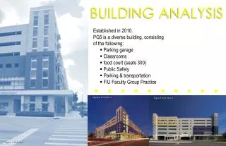
Building Geometry definition: • The building consists of 9 floors with average height of 3.4 meters except the storage floor which has 5.0 meters height. • This building has malty function stores for residential and commercial uses. • The overall area of this building is (5567) meter square distributed as follows: • The basements 279 m2. • First parking floor 245 m2. • second parking floor 555 m2. • Ground floor is 683 m2. • and 683 m2 for each one of 5 stores.
Philosophy of analysis & design Structural action (Forces): The structure is used for different uses. The five upper floors are used for residential purposes and the ground floor for residential and commercial uses and two parking floors and the last one for storage purposes.
:Material selection The selection of the material type depends on different factors such as: • Geometry. • Material availability. • Type and Quantity of loads. • Experience availability. • Economical factor. According to the above factors we will use Reinforced Concrete.
Material selection: • The reinforced concrete properties according to our structure are: • Compressive strength of concrete (𝒇'c ) • The compressive strength of concrete for slabsand beams is • fc= 24 MPa. • For columns, the compressive strength of concrete is fc= 28MPa. • Yielding strength of steel (fy) The yield strength of steel for flexural steel (main steel), shear reinforcement, torsion and shrinkage is fy = 420mpa.
Building code used: The building code used is ACI 318-08 (American Concrete Institute). Loads: Static loads include dead load, live load, super imposed loads, wall weight. Dynamic load include Earthquake loads.
Loads: Dead load = 5 KN/m2 Superimposed dead load on slab = 4.2 KN/m2 Wall weight =22kN/m Live load on parking = 6 KN/m2 Live load for residential = 2.5 KN/m2
For the dynamic load: In this section of our project, we analyzed the structure dynamically using RESPONSE SPECTRUM IBC2006 using the suitable parameters for Palestine and for the region where the structure is. • At first, we found the values of the parameters needed to analyze the building dynamically related to the location of our country, soil type and the way of building suitable for the workers which is ordinary.
SS spectral accelerations for short periodsS1 spectral accelerations for 1-second period
From IBC Map or from local building codes We can use Ss= .5 S1= .2
Calculate Response Accelerations:SMS = Fa·SS SM1 = Fv·S1Where: Fa and Fv are site coefficients
From the table we can get Fa= Fv= 1 • SMS = Fa·SS =.5 SM1 = Fv·S1 =.2 • Calculate the 5%-Damped Design Spectral Response Accelerations SDS = (2/3) SMS =0. 333 SD1 = (2/3) SM1=0. 133
Determine Seismic Response Coefficient, Cs Lesser of • Seismic Response Coefficient, Cs • Is a function of: • Spectral response acceleration • Site soil factors • Building Period • Response modification factors • Importance factor
Where: • R = Response Modification Factor • Ι = Seismic Importance Factor
This next figure shows identifying the parameters on response spectrum to get the dynamic analysis, and designing the structure depending on the results we got after analysis complete.
At first, we tried to define response spectrum to the whole structure to get the analysis and design based on it. But the model participating mass ratio was just 62.2% in X direction, and this reading still steady after the 6th mode until the 35th without increasing, so we decided to make a structural break between the two sides of the building and analyzing each side by itself as shown in the following figures to get modal participating mass ratio greater than 90%.
The modal participating mass ratio of the left side:We got more than 90% by the fourth modethe period T=1.25sec
The modal participating mass ratio for the right side:We got more than 90% by the seventh modeAnd the period T=1.51sec.
In graduation project 1, we analyzed the slabs as one way ribbed slab for the residential floors, and as one way solid slab for the parking and storing floors. We found the thickness and checked them for shear, compatibility, equilibrium and stress strain relationship and everything was right.After the dynamic analysis, nothing is changed because its loaded on the beam to the columns and footings which we modified to resist dynamic loads.
Type of beams: .1-Main Hidden Beams (1.2*.3) .2- secondary Beams(.3*.4) .3-Parameter Beams (1*.3) .65*.45).)4-primary drop Beams in the Parking And thenWe set the the primary Design from static load The dimension change due to dynamic load
Example of set primary Dimension Design of exterior beams • Let b = 40 cm, = 0.012 • Ln,max = 6.85m • Wu = 31*(3.55-0.6/2)+22+25*o.4*0.8 = 72 KN • Mu max = Wu*Ln2 /10 = 336KN.m • d² = Mn/Rb • d = 540mm, cover = 60mm, h = 600mm • beam weight = 0.4*(0.6-0.2)*25*1.2 = 4.8KN/m • Wu = 73KN/m
Design of the beams: we became more confident that the Sap is working in the same way that we work But faster than us So we take the Sap Design for the beams but when Sap Design that give us many station for the same member and for practical we take the max station and work on it.
Design of columns: Column in architecture and structural engineering is a structural element that transmits, through compression, the weight of the structure above to other structural elements below , in other words column is a compression member. For the purpose of wind or earthquake forces, columns may be designed to resist lateral forces. Other compression members are often termed "columns" because of the similar stress conditions. Columns are frequently used to support beams or arches on which the upper parts of walls or ceilings rest. In architecture, "column" refers to such a structural element that also has certain proportional and decorative features
Design of columns: The design of the columns should satisfy the architecture requirements. In statics we compare the area of steel from sap and the area of steel from hand calculation and found them closely to each other ,that because we have one ultimate axial force and one moment . But in Dynamic we have one ultimate axial load and two ultimate moment ,in this cause the Sap use 3D inter action diagram ,and that cant get from hand calculation because we just know 2D.
Design of columns: Conclusion: From the static result we found that the sap is working right but faster than us So we can depend on sap for both static and dynamic Design.
Problem: We have problem in the parking floor that the column is long column and we try to solve the problem by but braced beams .
Design of footing: Foundation design , including the selection of foundation system and the footing dimensions ,is strongly influenced by type of soil and its properties. As a result ,skilful foundation design blends knowledge of structural engineering and geotechnical engineering. The soil type is rock with qall=400KN/m^2
Type of footing used: 1- single footing. -2- wall footing. Footing area= Pu/qall. Q=
Thanks for listening

![[16469] Low Energy Building Design](https://cdn0.slideserve.com/984780/16469-low-energy-building-design-dt.jpg)