Download
1 / 21
220 likes | 348 Vues
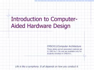
Introduction to Computer-Aided Hardware Design. Life is like a symphony. It all depends on how you conduct it. Life is like a symphony. It all depends on how you conduct it. Life is like a symphony. It all depends on how you conduct it. Use and Distribution Notice.

E N D
Introduction to Computer-Aided Hardware Design Life is like a symphony. It all depends on how you conduct it Life is like a symphony. It all depends on how you conduct it Life is like a symphony. It all depends on how you conduct it.
Use and Distribution Notice • Possession of any of these files implies understanding and agreement to this policy. • The slides are provided for the use of students enrolled in Jeff Six's Computer Architecture class (CMSC 411) at the University of Maryland Baltimore County. They are the creation of Mr. Six and he reserves all rights as to the slides. These slides are not to be modified or redistributed in any way. All of these slides may only be used by students for the purpose of reviewing the material covered in lecture. Any other use, including but not limited to, the modification of any slides or the sale of any slides or material, in whole or in part, is expressly prohibited. • Most of the material in these slides, including the examples, is derived from slides developed by Prof. Gao at the University of Delaware. Credit is hereby given to the author of these slides for much of the content. This content is used here for the purpose of presenting this material in CMSC 411, designed in a similar model.
Historical Perspective on Hardware Design • The market for digital hardware is an extreme market. It demands high performance, lower power consumption, and smaller footprint. • Technology is evolving at a fantastic rate. This includes an ever decreasing feature size, tighter VLSI integration, new mounting and new packaging technologies. • This demands a new design methodology… • must deal with greater complexity • decreasing time-to-market schedules
The New Design Methodology • We require… • increased efficiency • tools to capture, understand, and maintain a design • designs that are not open to interpretation • an open and widely used standard • portability and reusability • hierarchical design capabilities • modular design capabilities • easy of use for design, modeling, simulation
Enter VHDL • VHDL is a language for describing models of hardware systems (one of many – but the most popular). • Using VHDL and programmable hardware, we can use a fix step design process… • Define the requirements. • Describe the designs in VHDL. • Simulate the VHDL source code. • Synthesize, optimize and place-and-route the design for our target programmable device. • Simulate the post-layout design. • Program the target programmable device.
Design Requirements • To form a useable set of design requirements, we need to clearly identify and define the objectives and requirements. • functionality? • timing requirements? • set-up and hold times? • clock-to-output times? • minimal operating frequency? • critical path delays? • and so on…
Modern HardwareDesign Process • Simulation is a source code simulation using a VHDL simulator. • Synthesis flattens the hierarchical design and transforms it into a monolithic RTL representation. • Optimization then makes that monolithic design as efficient as it can. • Once that is done, the optimized design is subjected to a layout tool… • Fitting – this involves the translation from the RTL to a minimum sum of product expression for programming into a CPLD programmable device. • Place-and-route – this involves the translation from RTL to a FPGA device’s specific requirements.
Post-Layout Simulation • After the appropriate layout process has completed, timing information is now present in the design. • The synthesis and layout tools figure out timing characteristics based on the device being programmed. • This post-layout code can then be simulated to see if the finished device meets all of the design objectives. • If it does, excellent! • If not, a different target device could be used, or the VHDL code could be modified.
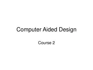
Test bench or other stimulus Waveform VHDL design Example Design Tool Flow Device selection Synthesis directives Synthesis software Netlist or equations Fitter or place & route routines Post- layout simulation model (VHDL or other format) Report file: resource summary; static timing analysis Device programming file: (for example, JEDEC format) Simulation software (VHDL or other simulator) Data file
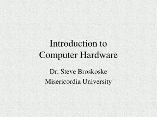
Logic Source: Dataquest Standard Logic ASIC Programmable Logic Devices (PLDs) Gate Arrays Cell-Based ICs Full Custom ICs CPLDs SPLDs (PALs) FPGAs Programmable Devices • SPLD – simple programmable logic device • CPLD – complex programmable logic device • FPGA – field programmable gate array
FPGAs • A FPGA is a field programmable gate array. • This is an array of logic cells that are connected via routing channels. • Each logic cell is programmable, as are the routing channels. • Each logic cell is a lookup table (LUT) with some registers. • Most FPGAs have special I/O cells and interconnections to onboard RAM. • Once the design has been subjected to place-and-route, the netlist is then given to a programming device which programs the FPGA. The FPGA then functions as our hardware until it is reprogrammed.
FPGA Advantages • FPGAs have a number of advantages • Good performance (they are fast). • High density and high capacity (they can act as large pieces of hardware). • They are easy to use. • They are programmable and reprogrammable (a huge amount of times). • They are not very expensive.
CPLDs versus FPGAs • A CPLD is a complex programmable logic device (like a PLA or PAL, but somewhat more complex). Complex Programmable Logic Device Field-Programmable Gate Array Architecture PAL/22V10-like Gate array-like More Combinational More Registers + RAM Density Low-to-medium Medium-to-high 0.5-10K logic gates 1K to 500K system gates Performance Predictable timing Application dependent Up to 200 MHz today Up to 135MHz today Interconnect “Crossbar” Incremental
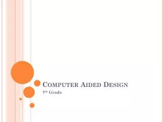
3 In-System Programming Controller JTAG Controller JTAG Port Function Block1 I/O I/O Function Block 2 I/O I/O Blocks FastCONNECT Switch Matrix I/O Function Block 3 Global Clocks 3 Global Set/Reset 1 Function Block 4 Global Tri-States 2 or 4 A Sample CPLD • Looking into a sample CPLD (XC9500)…
A Sample FPGA • Looking into a sample FPGA (the Xilinx XC4000)… Programmable Interconnect I/O Blocks (IOBs) Configurable Logic Blocks (CLBs)
C2 C1 C3 C4 H1 DIN S/R EC S/R Control G4 DIN SD G G3 F' Q D Func. G' YQ G2 H' Gen. G1 EC RD 1 H G' Y Func. H' S/R Control Gen. F4 F F3 DIN SD Func. F' F2 Q D XQ Gen. G' F1 H' EC RD 1 H' X F' K Complex Logic Blocks • Each XP4000 Complex Logic Block… • 2 four-input function generators (LUTs) - act as a 16x1 RAM or as logic function • 2 registers - Each can be configured as a flip/flop or a latch - synchronous and asynchronous Set/Reset
A B C D Z 0 0 0 0 0 0 0 0 1 0 0 0 1 0 0 0 0 1 1 1 0 1 0 0 1 0 1 0 1 1 . . . 1 1 0 0 0 1 1 0 1 0 1 1 1 0 0 1 1 1 1 1 Combinatorial Logic A B Z C D WE G4 G G3 Func. G2 Gen. G1 Function Generators / LUTs • Each function generator in the XC4000… Look Up Table 4-bit address • Capacity is limited by number of inputs, not complexity • Each function generator can act as 4 input LUT or as high speed synchronous dual port RAM
Input/Output Blocks • The I/O Blocks in the XC4000…
CLB CLB Switch Matrix Switch Matrix CLB CLB FPGA Routing • Most FPGAs have a routing network that connects the complex logic blocks and I/O blocks (in a programmable manner).
Design Flow for ASICs • Although we have discussed targeting programmable logic devices, VHDL can also be synthesized and subjected to layout for fabrication as an ASIC. • This requires a different set of tools but follows the same design process. • Typical flow… • Design in VHDL and simulate. • Synthesize and layout for FPGAs. • Simulate and then program FPGA. • Test the FPGA hardware. • Synthesize and layout for ASIC. • Simulate. • Send to fabrication.