Download
1 / 24
240 likes | 391 Vues
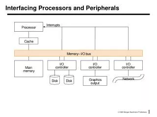
Interfacing Processors and Peripherals. I/O Design affected by many factors (expandability, resilience) Performance: — access latency — throughput — connection between devices and the system — the memory hierarchy — the operating system

E N D
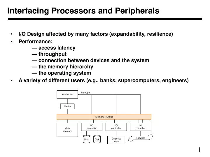
Interfacing Processors and Peripherals • I/O Design affected by many factors (expandability, resilience) • Performance: — access latency — throughput — connection between devices and the system — the memory hierarchy — the operating system • A variety of different users (e.g., banks, supercomputers, engineers)
I/O • Important but neglected “The difficulties in assessing and designing I/O systems have often relegated I/O to second class status” “courses in every aspect of computing, from programming to computer architecture often ignore I/O or give it scanty coverage” “textbooks leave the subject to near the end, making it easier for students and instructors to skip it!” • Somewhat GUILTY! — We won’t be looking at I/O in much detail — Read Chapter 8 — Recommendation: You should take a networking class!
I/O Devices • Very diverse devices — behavior (i.e., input vs. output vs. both) — partners (who is at the other end?) — data rates
I/O Techniques • Three main modes • Programmed I/O • CPU checks and reads and writes device buffers • Interrupt Mode • CPU asks devices to let it know when they are read • DMA • CPU asks devices to perform directly from memory • CPU sets the memory buffers • CPU is informed when I/O is done (or in case of an error) through an interrupt
I/O Example: Disk Drives To access data we need the following steps • Set DMA controller with address and count of words to be read • Ask disk to be on the right track and right position • Transfer Data to/from memory
DISK I/O Time • Preparation time: OS prepares/delivers the transaction controller • 1-2 ms. • Seek: position head over the proper track • On average takes 8 to 10 ms. • Rotational latency: wait for desired sector (.5 / RPM) • At 7200 RPM, time for 0.5 revolution is 4.2 ms. • Transfer time: grab the data and transfer to memory • At 4MB/sec, 4Kb takes 4KB/(4MB/sec) = 1 ms. • Total time: 14.2 ms to 17.2ms (min to max) • Say 15ms on average • Keeps bus busy for 1 ms out of 15 ms
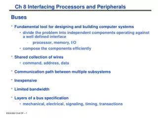
I/O Example: Buses • Shared communication link (one or more wires) • Difficult design: — may be bottleneck — length of the bus — number of devices — tradeoffs (buffers for higher bandwidth increases latency) — support for many different devices — cost • Types of buses: — processor-memory (short high speed, custom design) — backplane (high speed, often standardized, e.g., PCI) — I/O (lengthy, different devices, standardized, e.g., SCSI) • Synchronous vs. Asynchronous — use a clock and a synchronous protocol, fast and small but every device must operate at same rate and clock skew requires the bus to be short — don’t use a clock and instead use handshaking
Some Example Problems Bus Arbitration: — daisy chain arbitration (not very fair) — centralized arbitration (requires an arbiter), e.g., PCI — self selection, e.g., NuBus used in Macintosh, HPIB — collision detection, e.g., Ethernet
Some performance examples • Let’s look at some examples from the text • We are not going to include bus acquisition time • Processor runs at 200MHz, clock cycle time 5 nsec • Address transfer takes 1 cycles • Memory reads first 4 word block in 200 nsec (40 cycles) • Reads successive 4 word blocks in 20 nsec (4 cycles) • transfer of a 4 word block takes 10 nsec ( 2 cycles) • Successive read and transfers can be overlapped • There should be at least two cycles delay between bus cycles • To transfer 4 words it will take 1 + 40 + 2 + 2 = 45 cycles • To transfer 16 words it will take (successive reads and transfers can be overlapped) 1 + 40 + 4 + 4 + 4 + 2 + 2= 57 cycles • To transfer 256 words using • 4 words at a time will take 64 * 45 = 2880 cycles • 16 words at a time will take 16 * 57 = 912 cycles
Designing a bus system • A bus need to support • cache-memory traffic • I/O-memory traffic • Processor-I/O traffic • The first one depends on cache miss rate and replacement • The number of cycles for each transaction is to read a new line or write a dirty line back • For disk, each disk controller may support many disks • Disk controller is busy to initiate a transfer and to transfer data to/from memory for the actual data transfer (as opposed to whole transaction) operation (so 1-2 ms out of 15 ms or so in our earlier example) • Bus is only busy during actual transfer • Disk controller may transfer in burst mode (multiple bytes in one transaction)
Designing a bus system (Continued) • The bus should not be designed to keep it busy 100% of the time • Suppose a bus takes 200 processor cycles to transfer a 4-word (16-bytes) block in and out of memory (assume a 200 MHz processor) • Then it will take (4K/16)*200 = 50,000 cycles (it is really is a bit more, but we are simplifying) to transfer a 4K byte block • Processor and controller may take an additional 50,000 cycles to establish a transfer and complete it • They may use the bus for 10,000 cycle • A 4KB transfer keeps disk busy for 15ms (3,000,000 cycles) • A 4KB transfer keeps disk controller busy for 100,000 cycles • A 4KB transfer keeps processor busy for 50,000 cycles • A 4KB transfer keeps bus busy for 60,000 cycles • A New line (32 bytes) fetch keeps the bus busy for 200 cycles • A dirty line (32 bytes) write keeps the bus busy for 400 cycles
Designing a bus system (Continued) • Each disk can support 1sec/15ms = 66 4KB transfers/sec • Each controller can support 200M/100,000 = 2000 transfers/sec • Each controller can support 2000/66 = 30 disks • A processor can support 200M/50,000 = 4000 transfers/sec • However, the processor should not be busy with disk only • With 25% processor capacity, it can only support 1000 transfers/sec • Or number of disk that can be kept busy is 1000/66 = 15 • The bus can support 200M/60,000 = 3333 transfers/sec • Or it can support 3333/66 = 50 disks • However, the bus should not be loaded, say, more than 25% times with disk load, so it can really support only 12 disks • The number of disks is decided based on the critical resource • BUS HAS TO SUPPORT CACHE TRAFFIC BASED ON MISS RATE
Exceptions • Exceptions are just that – Changes in the normal execution of a program • Two types of exceptions • External Condition: I/O interrupt, power failure, user termination signal (Ctrl-C) • Internal Condition: Bad memory read address (not a multiple of 4), illegal instructions, overflow/underflow. • Interrupts – external • Exceptions – internal • Usually we can refer to both by the general term “Exception” though. • In either case, we need some mechanism by which we can handle the exception generated.
Virtual Memory and Exceptions • Virtual Memory TLB Misses • Page is just not in TLB • Bring page information into TLB • Page is not in Main Memory • Page Fault requires OS to intervene • Exception – Page Fault
Handling a Page Fault • Look up the page table entry corresponding to the virtual address to find the location of the referenced page on disk • Choose a page in main memory to replace • If that page has been written to in the past (dirty bit is set) • Recopy the page back to the disk • Move the new page into main memory from the disk • Step 2 may be very slow if page to be replaced is dirty • Step 3 will take millions of clock cycles to complete • So push this process to the side temporarily and do other meaningful work • Then later we can return from the exception handler and continue the program execution
Exceptions in the Exception Handler • Problem: What if another exception occurs within the exception handler itself? • Impossible to return to initial exception location, since EPC will be overwritten • Solution: Have the ability to turn off exception handling. • Set a bit that can disable other exceptions from affecting execution
I/O Devices and Exceptions • I/O devices will generate interrupts to notify the processor • Who will handle these interrupts? • Operating System • Provides interface to system I/O devices, so you don’t need to do all low-level operations • Provide some fairness in resource usage, as well as scheduling to improve throughput • Memory Mapped I/O versus Dedicated I/O instructions
Communication with I/O Devices • Reading and Writing to devices usually requires several steps • Status Registers • Hold information pertaining to the state of the device • Done bit or Error bit, etc. • May also be written to for notifying device when the data input is ready • Data Registers • Buffers for information • Examples: character to be printed, Ethernet packet, etc. • Some are only readable, others are only writeable. Sometimes they are both R/W. • User I/O is managed by the supervisor (kernel) level, since the device address space is not usually available to a user
Polling versus Interrupt-driven I/O • Polling • Processor must check whether or not I/O device has new meaningful information • Large overhead costs • Still sees some use though with very slow devices that are routinely used (e.g. mouse) • Interrupt-driven I/O • I/O device will notify processor by way of interrupt to request services • Not synchronous with instructions • Vectored Interrupts or EPC • Can have various interrupt levels to show priority
Direct Memory Access (DMA) • Memory/Device data transfers without constant use of the processor • DMA is the bus master, thus it directs the traffic • DMA Transfer • Processor must inform DMA of operation to perform along with the various parameters (e.g. device address, source address, destination address, bytes to transfer, …) • DMA starts the transfer and controls the bus, performing the requested operation • When the operation is done, the DMA controller sends an interrupt to the CPU to let it know the status of the transfer • There can be many DMA’s in the same system • Difficulties with virtual address translation • Coherency problem
MIPS Exception Related Information • Coprocessor 0 is used for exceptions in MIPS • P. A-32 in the textbook • 4 registers accessible by lwc0, mfc0, mtc0, swc0 • MIPS uses $k0 and $k1 as kernel registers for exception handling
Review Material • On Final Exam Key Points: • Number of cycles = n + k - 1 + bubbles • Forwarding unit does not insert bubbles • Hazard detection unit will insert bubble for anything that cannot be taken care by forwarding • Design of data placement algorithms for efficient caching • Distinction between design issues vs. programming issues • Multi-way set associativity is design • Placing data appropriately is programming • Memory Design will be a key issue • Include caching, virtual memory • And finally, I/O will be the major issue • It is comprehensive • Good Luck
Concluding Remarks • Evolution vs. Revolution“More often the expense of innovation comes from being too disruptive to computer users”“Acceptance of hardware ideas requires acceptance by software people; therefore hardware people should learn about software. And if software people want good machines, they must learn more about hardware to be able to communicate with and thereby influence hardware engineers.”