Download
1 / 75
840 likes | 1.92k Vues
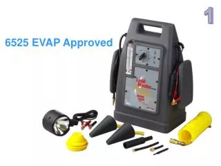
EVAP System testing using a Smoke Machine. Purpose. A smoke machine is used to identify leaks in systems that hold and transfer air and vapor. Usage. The primary function of the smoke machine is to test the integrity of the Evaporative Control System

E N D
Purpose • A smoke machine is used to identify leaks in systems that hold and transfer air and vapor.
Usage • The primary function of the smoke machine is to test the integrity of the Evaporative Control System • The smoke machine can also be used to detect: • Intake air system leaks • Exhaust system leaks • Cabin air/window seal leaks
Other Test Applications • Air cleaner assembly • Air ducts • Air valves • Component testing, prior to assembly • Diaphragms • EGR valve • Exhaust manifolds cracks • Fuel tank pressure sensor • Intercoolers • Intake gaskets • Injector o-rings • Loose clamps • Map sensors • Mass air flow meter • Oil leaks • PCV valve and hoses • Throttle body shaft • Turbochargers • Vacuum hoses • Vacuum switches
Visible smoke pinpoints the leak source • A leak in the vapor recovery system can be easily identified by the presence of smoke at the gas cap
Smoke machine components Large tailpipe plug Smoke oil Smoke dispersal adapter UV light source 12 volt power cables Vacuum pump adapter Wireless remote UV glasses Exhaust pipe cone adapter Smoke outlet hose Plugs EVAP test port adapter Schrader valve removal tool
Smoke oil • The smoke machine generates smoke by passing mineral oil over a red hot electric heating coil • The oil contains a chemical that glows bright yellow when exposed to Ultra Violet [UV] light
Ultraviolet Light source • An LED type UV flashlight is used to pinpoint the source of leaks • Condensed smoke oil will glow green/yellow when exposed to UV light
Never look directly into the UV light • Yellow UV safety glasses should be worn whenever working with UV light sources • Exposure to UV light can cause permanent damage to the retinas of your eyes
Condensed smoke oil • A small amount of smoke vapor will condense around the places that the smoke leaks out of. This liquefied smoke will glow • Smoke vapor will generally not glow when exposed to UV Light
Check the oil supply • A dipstick is attached to the smoke machine’s oil filler cap • Unscrew the dipstick and observe the level of oil using the UV light to illuminate the dipstick
Checking the oil Full Mark • Smoke oil is a clear liquid so it is difficult to see the level on the dipstick without the aid of UV light
Adding oil • If the oil level is low add a few ounces of oil – do not overfill
Connect to the battery • The smoke machine is powered by the vehicles battery via the 12 volt power leads at the back of the machine
Hanging the smoke machine • When the smoke machine will be used near the engine the machine can be hung from the hood latch
Air Line coupler • The correct type of coupler needs to be installed to connect the smoke machine to the shop’s compressed air hoses
Shop air fitting • Compressed air from the shop’s air compressor is used to push the smoke through the system being tested • The correct air coupler fitting needs to be attached to the smoke machine
Vapor hose • The vapor hose is used to inject smoke into the system being tested
Cone adapters • Rubber cones allow the vapor line to connect and seal to a variety of different size and shaped openings • The large cone adapter here is used to connect the vapor hose to the exhaust pipe
Plugs • Plugs may be needed to seal opening where components have been removed or where a small amount of leakage is expected
Air Diffuser • To find air leaks around windows and doors an air diffuser is used to spread out the smoke • The vehicle’s HVAC fan is set to high speed while smoke is blown over the edges of the windows and doors • Any disturbance in the smoke may indicate an air leak
Adapter for EVAP test port • Most late model cars have an EVAP system test port that uses an ACME thread [similar to the fitting on tank of R134a refrigerant.
EVAP test port • The EVAP test port is located on the vapor line between the purge solenoid and gas tank • The cap is normally a light green color • The port is normally located under the hood but is occasionally found underneath the car
Vacuum pump port • The auxiliary output port can be used to connect a hand held vacuum pump to the smoke machine • Some EVAP systems use electro mechanical vacuum pump located inside the fuel tank to monitor EVAP system integrity • A source of vacuum is needed to test the operation of the sensors and pump
Vacuum Pump • During the test a small amount vacuum is applied using a hand held vacuum pump
Function select buttons • There are 3 membrane switches on the right side of the panel • The display select button changes the units of measurement displayed by the 3 digit LCD matrix • The orifice select button changes the size of the flow restriction inside the smoke machine • The start button starts a 5 minute leak down test and toggles the machine between full flow and pulsed flow
Display Indicator lights • When illuminated an ‘Orifice Leak Size’ of .040”, .020” or .010” will be indicated on the LED display • When the ‘Flow L/M’ is illuminated the LED displays the smoke flow rate in liters per minute • When ‘Pressure in H2O’ is illuminated the LED displays system pressure in inches of water
Display Indicator lights • The ‘Vacuum in H2O will only illuminate when the smoke machine senses that the system pressure is lower than ambient atmospheric pressure • The ‘Polarity Protect’ indicator will illuminate if the power lead connections at the battery are reversed
Display Indicator lights • The ‘Pass’ or ‘Fail’ light will illuminate after a 5 minute leaks test has been completed • The three orifice size indicator lights indicate the size the internal restriction in the smoke machines output port
Display Indicator lights • The ‘Off/Decay’ light indicates that flow of smoke from the machine is turned off • When the ‘On’ light is illuminated there should be a continuous flow of smoke passing through the smoke vapor hose • The ‘Low Flow’ indicator light indicates that the machine is operating in pulsed mode. A puff of smoke is sent through the smoke vapor hose every few seconds.
Inches of Water • Very low levels of pressure or vacuum are measured in units of inches of water • The amount of vacuum applied to the tip of a straw that will cause the water in the straw to rise one inch equals a vacuum level of 1 inch H2O
Inches of water - pressure • Pressure can be measured in inches of water using a manometer • A ‘U’ shaped glass tube is partially filled with water • One end of the tube is open to atmospheric pressure • The other end is connected to the pressure being measured • The difference between the water levels is measured in inches Pressure source Open to atmosphere
Select the type of gas • After the power leads are connected to the battery you have 5 seconds to select the type of gas being used in the test. • The default value is ‘AIR’ = shop air • If you are using compressed nitrogen gas press ‘Display Select’ until ‘n2’ is displayed • If you are using compressed carbon dioxide press ‘Display Select’ until ‘CO2’ is displayed
Select the display type • Pressing the ‘Display select button cycles through the three types of data displays: • Orifice Size • Flow rate • Pressure / Vacuum • If you are performing a pass/fail leak test the display must be set to orifice size to finish the test • When the display is set to pressure the vacuum LED will illuminate if the system pressure is below the ambient atmospheric pressure
Start button functions • Pressing the ‘Start’ button will begin sending a steady stream of smoke through the smoke/vapor hose • This begins a timed 5 minute test of the EVAP system • Pressing the ‘ Start’ button a second time will set the smoke machine to pulsed low flow mode • While in ‘Low Flow’ mode the smoke machine will make a clicking noise
Turning off the machine • The machine will automatically shut down after the completion of the 5 minute test or after 8 minutes of inactivity • Holding the ‘Start’ button depressed for a few seconds will force the machine into shutdown mode
Low battery voltage warning • A ‘Lo bAt’ warning message will be displayed if the battery voltage level is below 11.0 volts Lo bAt
Remote start/stop • The smoke machine comes with a remote key fob that is used to start and stop the flow of smoke
Max Pressure and Flow Rate • Maximum smoke pressure = 13.0 inches of H20 • Maximum flow rate = 10 liters per minute
OBDII EVAP System EVAP test port Purge Solenoid Vent Solenoid Charcoal canister Intake manifold Sealed gas cap EVAP Pressure sensor Roll over valve Pressure release valve Fill limit vent valve
Canister and vent solenoid • The charcoal canister and vent solenoid are located under the vehicle and within a few inches of the fuel tank Vent to atmosphere Charcoal canister Vapor line to tank Purge line Vent solenoid
Purge line connects to canister Purge solenoid • The purge solenoid controls the rate at which gasoline vapors are removed from the canister during the drive cycle • It is normally found under the hood
EVAP Monitor • All OBDII systems run a non-continuous monitor on the evaporative emissions system at least once in every trip • There are two test performed in the EVAP system monitor: • A system integrity [leak] test • A system performance test [flow test]
EVAP Monitor • If either test fails in two consecutive trips the Check engine light will illuminate and a code will be set • EVAP system codes range from P0440 through PO470
EVAP System integrity test phase 1 Purge Solenoid - open • During the first phase of the test the PCM commands the vent solenoid closed and pulses the purge solenoid to create a partial vacuum within the tank Vent Solenoid - closed EVAP Pressure sensor
EVAP System integrity test [leak test] • After enabling criteria are met the PCM commands the canister vent solenoid closed and sends a PWM current [pulse width modulated] to the purge solenoid to allow a small partial vacuum to build up inside the gas tank • When the pressure inside the tank reaches a preset amount – typically around 10 inches of water – the purge valve is commanded closed • Pressure inside the tank is monitored for the next few minutes
EVAP System integrity test phase 2 Purge Solenoid - closed • When the pressure sensor reaches a preset value the PCM closes the purge solenoid. The vent solenoid remains closed. The PCM monitors the change in pressure inside the tank for the next few minutes. Vent Solenoid - closed EVAP Pressure sensor
EVAP monitor – system integrity test • If there is a rapid rise in tank pressure after the purge solenoid closes there must be a large leak – greater than .040” . The EVAP integrity test fails. • If the tank pressure slowly rises over a period of several minutes the total leak size must be smaller than .020”. The EVAP integrity test passes. • The EVAP monitor then begins the system flow test.
EVAP monitor – flow test Purge Solenoid - cycling • The flow test looks at the changes in short term fuel trim as the duty cycle applied to the purge solenoid is altered by the PCM. Vent Solenoid - open Upstream oxygen sensor