Download
1 / 42
420 likes | 430 Vues
NPARC Flow Simulation System. What is NPARC?.

E N D
What is NPARC? • The NPARC (National Project for Application-Oriented Research in CFD) Alliance is a partnership between NASA GRC and the U.S. Air Force AEDC, with significant participation from Boeing, dedicated to providing an applications-oriented computational fluid dynamics (CFD) capability for the U.S. aerospace community, centered around the NPARC Flowfield Simulation System. • The NPARC Vision: The Computational Tool of Choice for Aerospace Flow Simulation
NPARC Alliance History 1993• Formation of NPARC Alliance 1994-96• Significant development of NPARC leads to large user base 1996• McDonnell Douglas becomes an active partner • Code development groups at AEDC merge • Decide to merge NPARC, NASTD, NXAIR into WIND 1997 • Work begins on the NPARC Alliance Flowfield Simulation System centered on the WIND Navier-Stokes Code • McDonnell Douglas merges with Boeing 1998• WIND Version 1.0 released 1999• WIND Version 2.0 released • NASA Software of the Year Honorable Mention winner 2000• WIND Version 3.0 released 2001• WIND Version 4.0 released 2002• WIND Version 5.0 released • BCFD (unstructured grid version) released to the Alliance
Alliance Organization AEDC GRC Executive Direction Committee Jere Matty Manager Mary Jo Long-Davis Manager Technical Liaisons Greg Power Technical Lead Nick Georgiadis Technical Lead NPARC Steering Committee Bonnie Heikkinen Support Lead John Slater Support Lead Ray Cosner (Boeing - PW) Technical Direction Committee Chris Nelson Development Lead Charlie Towne Development Lead Ted Reyhner (Boeing-Commercial) Ken Tatum Validation Lead Julie Dudek Validation Lead Bob Bush (UTRC)
Flow Simulation System • The NPARC Flow Simulation System has at its core the WIND CFD solver, but also consists of… • common, portable file structure • pre-processing utilities to set up the simulation • post-processing utilities for examining the results • web-based version control software • web-based documentation • web-based validation and verification archive • The NPARC Flow Simulation System assumes that the grid is generated using some other software system (i.e. ICEM CFD, Gridgen).
Supported Platforms Silicon Graphics - IRIX 6.5, R4400, R5000, R10000, R12000, R14000 processors - Multi-processing IRIX 6.5, R10000, R12000, and R14000 processors Hewlett-Packard - Multi-processing HPPA11, PA-8500 processor Sun - SunOS 5.x, SPARC4U processor - Multi-processing SunOS 5.x, SPARC4U processor Linux, X86 processor
Utilities RESPLT Flow Simulation System Grid Generator Create Grid Set Boundary Conditions Download Code GMAN IVMS Convert File Formats Mirror Zones Split/Merge Zones Reorder/Delete Zones Wall Function Pre-Processor Run Flow Solver WWW Documentation Validation WIND CFPOST Monitor Convergence Examine Results Post-Processor
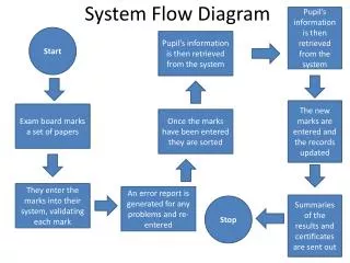
Class Flowchart run.ic.q(PLOT3D initial solution file) CFCNVT (convert files) run.x(PLOT3D grid file) run.cgd(common grid file) run.cfl(common solution file) GMAN (set boundary conditions) run.cgd(common grid file with BCs set) run.mpc(multiprocessor control file) run.dat(data input file) WIND (solve flow) run.cgd(common grid file) run.lis(list output file) run.cfl(common solution file) RESPLT (read residuals) CFPOST (plot and process) nsl2.gen(GENPLOT file of NS residuals) run.q(PLOT3D solution file) output.gen(output GENPLOT file) output.lis(output list file) Indicates an optional file
Primary Parts of the System CFCNVT Converts the PLOT3D grid and solution files (run.x, run.ic.q) into the common file format (run.cgd, run.cfl). GMAN Reads the common grid file and allows for manipulation of the grid and setting of boundary condition types onto zone boundaries and overlapping regions. WIND Solves the flow equations with inputs from the common files and input data file. Outputs the solution to the common solution file and creates a list output file. RESPLT Reads the list output file and generates GENPLOT files of convergence histories. CFPOST Post-processor. Reads the common grid and solution files and lists flow field variables, integrates fluxes and forces, creates and plots line and surface GENPLOT files, creates PLOT3D files, and generates output reports.
Other Utilities B4WINDGUI interface for converting NPARC files to WIND common file format CFBETACreates a mirror image of the grid for sideslip (beta) cases CFCOMBINECombines zones of common grid and solution files for which grid points match CFREORDERDeletes and reorders zones from the grid or solution file CFSPLITSplits a zone of the common grid and solutions files FPROPerforms manipulations of the common solution file GPROPerforms grid generation and manipulation JORMAKCreates a *.com file containing the solid boundaries for analyzing the surface properties TIMPLTReads a common time history file (.cth) and creates a GENPLOT file CFSEQUENCEExtracts a sequence grid and solution from existing files CFSUBSETRemoves grid points from the log-layer for wall function applications ADFVIEWER From the CGNS project, is an ADF file viewer and editor with a nice GUI interface MADCAPReplacement for GMAN and a unified GUI for many of these utilities Plus several more utilities that are listed and explained in the online documentation
IVMS • Internet Version Management System • (IVMS) used for software version • control and for distribution of • software to users • Accessed via the WWW • GUI interface based on RCS, • developed at Boeing • Users can easily download current • (and earlier) versions of WIND • and its associated utilities • Allows collaborative development at • multiple sites
Code Distributions WIND Application Distribution - Contains the executable programs and files needed to run WIND on a specific supported platform. WIND Build Distribution - Contains all source code needed to build the code, plus Makefiles for several platforms. Tools Distribution - Contains executables for the pre- and post-processing tools used with WIND, including GMAN and CFPOST, for a specific supported platform. Tools also available individually as source code, with Makefiles.
Availability • NPARC Alliance software is available at no cost to U. S. companies, • government agencies, and universities. • May not be used for contract work with a non-U. S. organization. • Release point is through AEDC. • Non-government organizations must have an Export Control Number, • i.e., be registered with the Defense Logistics Services Center Joint • Certification Program. • See the “Acquiring the Software” link on the NPARC Alliance • home page (www.arnold.af.mil/nparc) for details and application • forms, or send email to nparc-support@info.arnold.af.mil. • Approved users download the software from the IVMS web site.
WIND Access at NASA Glenn • Source and executables for WIND, and the various tools, are available from zargon via automount (contact Charlie Towne). • Requires setting of environment variables in .login file. • Executables for SGI, Sun, and Linux. • Run without installing on your own system. • Run codes using scripts. • For details see “WIND at NASA Glenn” in the WIND Installation Guide, at http://www.grc.nasa.gov/www/winddocs/install/grc/grc.html • WIND can be installed from tar file of Application distribution. • Installation documentation is available at http://www.grc.nasa.gov/www/winddocs/install
Documentation • All documentation is available at • www.grc.nasa.gov/www/winddocs • in both HTML and PDF formats • WIND User’s Guide - Describes the • operation and use of the WIND code, • including a tutorial, and descriptions of • the physical and numerical models, • boundary conditions, convergence • monitoring, files, run scripts, parallel • operation, and input keywords • Separate user’s guides for GMAN and • CFPOST, and for several smaller • utilities distributed with WIND
Additional Documentation • WIND Installation Guide - Describes how to download and install the executables for WIND and its associated “tools,” how to build a new executable from the WIND source code, and how to access WIND via automounthere at GRC. • WIND Developer’s Reference - Contains detailed information about the structure of the WIND code useful for those modifying the code (only available to WIND users). • Common File User’s Guide - Detailed information about the common file library, a set of routines providing access to common files. • Guidelines Documents - Programming, documentation, and testing guidelines created for use by the NPARC Alliance during software development projects.
Verification & Validation • NPARCAlliance Verification & • Validation (V&V) WWW site at • www.grc.nasa.gov/www/wind/valid • Validation archive presents WIND code • results; all input/output files may be • downloaded. • Verification cases present comparisons of • CFD results with exact analytical or • computational results. • Validation cases present comparisons • of CFD results with high-quality • experimental data. • Includes detailed examples showing how • to set up and run a case, using GMAN, • WIND, CFPOST, and other WIND utilities.
Support • NPARC Alliance Support Team provides direct user support via email • (nparc-support@info.arnold.af.mil) or telephone (931-454-7455). • National user’s meetings once a year (AIAA Aerospace Sciences Meeting) • Dedicated technical paper session (AIAA Aerospace Sciences Meeting) • Training classes. • Annual newsletter (The Predictor / Corrector). • Annual Workshop produces Policies and Plans document. • User’s mailing list (nparc-users@info.arnold.af.mil). • NPARC Alliance WWW site (www.arnold.af.mil/nparc). • Online documentation (www.grc.nasa.gov/www/winddocs).
Code Development • Development of WIND and utilities is continuous (Boeing, AEDC, NASA GRC). • GRC efforts focused on developing tool for simulating inlet and nozzle flows (VG model, turbulence, bleed). • Development efforts / contributions / suggestions by users are encouraged for all aspects of the system. • IVMS allows distributed development while maintaining strict version control.
Future Activities • Unstructured and hybrid grids. BCFD was released to Alliance and we will be running cases to learn how to use it. • Enhanced physical modeling capabilities: turbulence, transition, chemically reacting flows, boundary conditions, vortex generators. • Complete conversion to CGNS database format. Version 5 capability will be tested. • Consolidation of tools under a common GUI (MADCAP). This will eventually replace GMAN. • Investigate framework options for future CFD systems and multi-disciplinary applications (store-drop, aeroelasticity, structures).
Class Flowchart run.ic.q(PLOT3D initial solution file) CFCNVT (convert files) run.x(PLOT3D grid file) run.cgd(common grid file) run.cfl(common solution file) GMAN (set boundary conditions) run.cgd(common grid file with BCs set) run.mpc(multiprocessor control file) run.dat(data input file) WIND (solve flow) run.cgd(common grid file) run.lis(list output file) run.cfl(common solution file) RESPLT (read residuals) CFPOST (plot and process) nsl2.gen(GENPLOT file of NS residuals) run.q(PLOT3D solution file) output.gen(output GENPLOT file) output.lis(output list file) Indicates an optional file
WIND Files Principal Input Files Input Data File (*.dat). Contains keyword input describing the flow problem and how WIND is to be run. (ASCII file) Common Grid File (*.cgd). Contains the computational grid (x,y,z) and boundary condition types and zone coupling data set using GMAN. (binary file) Principal Output Files List Output File (*.lis). Contains listing of input parameters, job statistics, error messages, residuals and integrated convergence information. (ASCII file) Common Flow File (*.cfl). Contains the flow, turbulence, and chemistry field, as well as reference state and basic information on simulation. (binary file) Common File Format (CFF) • Used for common grid (*.cgd) and flow (*.cfl) files. • Also used for some other WIND-related files. • Self-documenting database structure developed at Boeing. • Compact, easily accessible, portable. • Common grid and common Flow files supported by several commercial grid-generation (ICEM, Gridgen) and post-processing packages (Fieldview). • CGNS now supported.
WIND Files (cont) Other / Optional Input Files • Multi-processor control file (*.mpc) • Chemistry Input file (*.chm) • WIND Stop File (NDSTOP) • Transition and temperature specification files Other / Optional Output Files • Global Newton file (.cfk) • Boundary data file (.tda) • Time history file (.cth) Further information is in WIND User’s Guide: www.lerc.nasa.gov/www/winddocs/user/files.html
CFCNVT • Common File Convert (CFCNVT). • Converts several file formats to the common file format for WIND. • Grid and flow files can be converted. • Flow file can be used as initial condition for flow field in WIND. • Text-based program can be run interactively or in batch. • Reply to a few prompts depending on the input file format. • Start analysis process assuming we have a grid file. • PLOT3D format (option 11) is a common grid file format output by grid generation software. • An initial flow field can be generated with another small program, output to the PLOT3D format, and then converted to a common flow file using CFCNVT.
GMAN • Grid Manager (GMAN). • GMAN can be run in interactive mode using graphical menus or commands or in batch mode using scripts. • Input is the common grid file (*.cgd). • Switching to graphics mode is done by “swi” or “switch”. • Journal file is output for rerunning GMAN in batch mode. What does GMAN do? Set units for grid and flow (EE or SI) Set boundary condition types Display grid and boundary condition types Compute zonal connectivity Perform hole-cutting and grid overlapping Scale, translate, rotate grid Add or replace zone from other file Basic grid generation (seldom used) Red boxes indicate inputs to prompts The MADCAP program will eventually replace GMAN
GMAN: Graphics Mode Quick Reference: • Hierarchy of menu items is from top to bottom. • Left mouse button selects a menu item. • A line through a menu item indicates that item can’t be chosen. • A “*” in front of a menu item indicates that item is the default. • Mouse Buttons in Display: LEFT: Rotation MIDDLE: Zooming RIGHT: Translation
GMAN: Boundary Conditions BC types available: Undefined Reflection Freestream Viscous wall Arbitrary Inflow Outflow Inviscid Wall Self-Closing Singular Axis Mixed-Axis Wall Bleed Pinwheel Axis Frozen Chimera Boundary • GMAN is used to assign boundary condition types to each grid point on a zonal boundary. • Zonal boundaries: I1, IMAX, J1, JMAX, K1, KMAX • Subregions of boundary grid points can be defined to specify multiple BC types on a zonal boundary. • Process for specifying BC type: • Select zone (i.e. zone 1) • Select boundary (i.e. K1) • Select subregion (i.e. j1 j21 i2 i14) optional • Select BC type • Update file Sample of journal file created created during an interactive session with GMAN Green = viscous wall Aqua = bleed region
GMAN: Zonal Connectivity • Flow information is exchanged across zonal boundaries. • Connectivity defines how a zonal boundary is connected to other zonal boundaries. Types of Zonal Connectivity 1) Abutting, Point-to-point match 2) Abutting, Non point-to-point match 3) Overlapping, Point-to-point match 4) Overlapping, Non point-to-point match 1 & 3 2 Outer boundary 4 • GMAN can automatically compute zonal connectivity for abutting (1 & 2). • Overlapping (overset) grids use tri-linear interpolation to exchange information. • Point-to-point match is best since direct transfer is possible and interpolation errors are minimized. Interior boundary
GMAN: Overlapped Grids Hole Fringe points • Example of NLR Airfoil with flap • Flap grid overlaps airfoil grid. • Use flap grid to cut a hole in airfoil grid. • Indicate edge points of cut are fringe points to interpolate boundary information from flap grid solution. • Outer edge of flap grid is fringe boundary of flap grid and receives interpolated data from the airfoil grid. Fringe points
WIND Equation Sets in WIND: Reynolds-Averaged Navier-Stokes (RANS) Turbulence Chemistry Magneto-Fluid Dynamics (MFD) • WIND is not an acronym. • Solves several types of equations. • Contains variety of features and numerical methods. • Basic input files required are: Input data file (*.dat) Common grid file (*.cgd) Common solution file (*.cfl) optional • WIND is executed using the WIND script with text prompts and responses. • WIND is run as a batch execution. • Simulation times to iterative convergence can range from minutes to days. Features of WIND: Cell-vertex, finite-volume formulation Time-marching (steady or unsteady) Space-marching for supersonic flows Propulsion-specific boundary conditions Multi-zone, structured grids Abutting or overlapped zones Parallel and multi-processor operation
First 3 lines are for titles. Example Input Data (*.dat) file: RAE 2822 Airfoil. 2D Transonic Flow. Mach = 0.729. Alpha = 2.31 deg. Single zone C-grid 369 x 65. /Freestream Mach p(psi) T(R) AOA Beta freestream static 0.729 15.8 460.0 2.31 0.0 downstream pressure freestream zone 1 turbulence model spalart allmaras dq limiter on implicit boundary on cycles 200 iterations per cycle 10 print frequency 10 cfl 5.0 end “/” indicates a comment line . Freestream keyword sets reference conditions, which are input in units consistent with grid file. Specifies choice of turbulence model. Specifies additional information for the outflow boundary condition. Specifies the number of cycles to run. Specifies use of limiter for change in solution (dq) over an iteration. Specifies use of implicit boundary conditions on the airfoil surface. Specifies the CFL number. Specifies the number of iterations per cycle and print frequency to list output file. WIND: Input Data File • Input data file (.dat) is ASCII file. • File contains descriptive keywords. • “test” options used for special cases. • Online documentation lists all keywords.
WIND: Select Keywords Some of the other most commonly used keywords include: AXISYMMETRIC Indicates flow domain is planar, axisymmetric. BLEEDSpecifies inputs for mass flow and porous bleed models. FIXERTurns on algorithm to fix bad points in flow (I.e. negative pressure). IMPLICITSpecifies algorithm to use for implicit time-marching. MASS FLOWSpecifies inputs for outflow boundary condition. RHSSpecifies algorithm to use for numerical flux. SEQUENCEOption to use coarser grid that is sequence of full grid. SMOOTHINGSpecifies algorithm for artificial dissipation. THIN SHEAR LAYEROption to use thin shear layer assumption. TVDSpecifies algorithm for TVD limiting of flux terms. WALL FUNCTIONOption to use a wall function for turbulence modeling.
WIND: Block Keywords Block keywords are input as a block of keywords that follow a certain format: ARBITRARY INFLOWProves inputs for the arbitrary inflow boundary condition CHEMISTRYProvides inputs for the chemistry model LOADSProvides inputs for summing forces on surfaces ACTUATOR / SCREENProvides inputs for the actuator disk / screen model VORTEX GENERATORProvides inputs for the vortex generator model arbitrary Inflow total hold_totals zone 1 uniform 0.6 14.0 460.0 0.0 0.0 endinflow loads print totals zones lift frequency 10 reference area 1.0 reference length 1.0 reference moment center 0.0 0.0 0.0 zone 1 subset I 33 337 j 1 1 k 1 1 force noslip endloads chemistry fuel air ratio 1.0 file h2air-7sp-std-15k.chm finite rate mass fractions 0.993 0. 0.007 0. 0. 0. 0. endchemistry
WIND: Flow Initialization WIND requires an initial flow field to start the marching schemes. Some options for obtaining this include: • Default initialization is uniform flow based on “freestream” values. • Initial flow solution can be from common solution file (*.cfl). • Arbitrary inflow can initialize a zone. • Boundary layer initialization on a wall (one j or k surface per zone). • Re-initialization of a “bad” zone. • Initialization of turbulence and chemistry values.
WIND Script • Command-line script to run WIND. • Graphical interface also available (B4CFD). • WIND may be run interactively, via Unix at/batch commands, or via NQS system. • Executable need not reside on local system. • May run on a remote system. • Type wind –help to get list of options.
WIND: Parallel Operation • WIND may be run in parallel on a multi-processor system, or on a cluster of heterogeneous systems. • Fault-tolerant master-worker approach. • Grid zones are distributed from the master to the worker systems for processing. • PVM message passing is used on clusters; PVM or MPI may be used on multi-processor systems. • WIND and PVM / MPI need not be pre-installed on worker systems. • User specifies hosts via Multi-Processing Control (*.mpc) file. Multi-Processing Control (*.mpc) file: # loadlimit 1800 host saturn nproc 12
WIND: New in Version 5 • Version 5 released November 2002 • Improved time history tracking • Improved CGNS compatibility • Vortex generator model • Direction specification at arbitrary inflow boundary • Improved smoothing algorithm • Chemistry improvements • OVERFLOW options - Time step selection - ARC3D 3-factor diagonal scheme - Roe differencing • Koren and van Albada TVD limiters • Additional explicit operators
RESPLT • RESPLT: Residual Plotter. • Reads the List Output File (*.lis) and extracts residual and other iterative convergence information and creates an ASCII GENPLOT file (*.gen) for plotting by CFPOST. • Text-based program can be run interactively or in batch. • Reply to a few prompts depending on what information is to be extracted. • Asks for the name of the GENPLOT file to output. Red box indicate inputs to prompts Sample of Selections: 2 L2 norm of residual of RANS equations per zone 23 L2 norm of residual of Spalart-Allmaras turbulence equation 17 Lift on surfaces as indicated by the LOADS keyword
RESPLT: CFPOST Plotting Airfoil lift –vs- Cycles RANS L2 residual –vs- Iterations CFPOST can then plot the ASCII GENPLOT file.
CFPOST • CFPOST: Common File Post-Processor. • Text-based program requires sequence of commands and can be run interactively or in batch. What does CFPOST do? Plots GENPLOT files Creates contour plots Creates velocity vector plots Outputs PLOT3D grid & solution files Computes forces and moments Integrates fluxes (mass, momentum, …) Averages flow over a cut or surface Propulsion-specific analysis (rakes) 3D flow visualization is better performed using packages such as FAST, Fieldview, or Ensight. Prompt waiting for commands
CFPOST: Command Sequence To plot a GENPLOT file: plot data nsl2.gen quit General sequence of CFPOST commands: 1) Specify grid file 2) Specify solution file 3) Specify units 4) Specify zone 5) Specify surface, cut, subset, etc… 6) Specify operation (plot, integrate, …) 7) quit to exit To create PLOT3D files: grid run.cgd solution run.cfl units fss zone 1 to last subset i all j all k all plot3d x run.x q run.q unformatted mgrid quit To create a report of forces on a wing: grid run.cgd solution run.cfl units fss zone 3 subset k all i all j 1 integrate force output forces.lis – iviscous – reference length 1.0 – reference area 1.0 – reference moment 0.0 0.0 0.0 quit To create a plot file of Cp distribution at a cut along a wing: grid run.cgd solution run.cfl units fss zone 2 subset i all j 1 k all cut at z 0.25 variables x; Cp scale –1 genplot output cp.gen quit
Summary of the System • Many options exist for using the programs that make up the NPARC Flow Simulation System. • The previous presentation discusses one approach: CFCNVT GMAN WIND RESPLT CFPOST • Online documentation provides further information. • Best way to learn is to see a demonstration and get some hands-on experience (next few hours).