Download
1 / 41
410 likes | 412 Vues
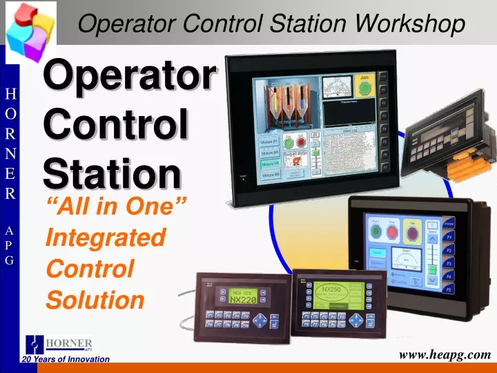
Operator Control Station Workshop. Operator Control Station. “All in One” Integrated Control Solution. Logic Controller Basics - 101. Programmable Controller A set of coded instructions that enables a machine, especially a computer, to perform a desired sequence of operations.

E N D
Operator Control Station Workshop OperatorControlStation “All in One” Integrated Control Solution
Logic Controller Basics - 101 Programmable Controller • A set of coded instructions that enables a machine, especially a computer, to perform a desired sequence of operations. • To provide (a machine) with a set of coded working instructions. • To train to perform automatically in a desired way. • To prepare an instructional sequence I/O (Inputs / Outputs) • Input and Output communication between a controller and its "peripherals". Program (RLL) • Relay Ladder Logic. Similar to a one line electric diagram. Operator Interface • A device to let an operator monitor and adjust parameters on a machine or process through the controller. Networking • Interconnecting Controllers, Operator Interfaces and I/O to allow them all to communicate as one system.
Basic Controller SCAN - Block Diagram Programming Device INPUT TABLE USER PROGRAM OUTPUT TABLE Central Processing Unit (CPU) DATA STORAGE Input Devices Input/Output Modules Output Devices
Banner Prox Controller Sweep Components Input Update Logic Execution ( ) 1 0 1 0 0 1 0 0 1 1 1 0 0 0 1 1 1 0 1 0 0 1 0 0 1 1 1 0 0 0 1 1 Output Update Communication and Diagnostics Output Image Table Input Image Table
Data Types : by the numbers BINARY 16384 8192 4096 2048 1024 512 256 128 64 32 16 8 4 2 1 0 = 0000 1 = 0001 2 = 0010 3 = 0011 4 = 0100 5 = 0101 6 = 0110 7 = 0111 8 = 1000 9 = 1001 A = 1010 B = 1011 C = 1100 D = 1101 E = 1110 F = 1111 BIT NIBBLE BCD HEX BYTE WORD
Bits - Bytes - and Words • A Bit is One Decimal • It is either a 1 or a 0. • On or Off, In Alarm or Not in Alarm • A Byte is 8 Bits. • +127 to -128 • A Word Is 2 Bytes or 16 Bits • +32767 to -32768 ex. 00000000 00100101 = +37 • (used for Analog and Register values) • (sign bit) 16384 8192 4096 2048 1024 512 256 128 64 32 16 8 4 2 1 • 16 15 14 13 12 11 10 9 8 7 6 5 4 3 2 1 Bit Value Bit Place
Bits - Bytes - and Words Examples 00000000 00000000 = 0 11111111 11111111 = 00000000 00000001 = +1 00000000 00000010 = +2 10000000 00000000 = 00000000 00000011 = +3 00000000 00000100 = +4 00000000 01100111 = +103 01111111 11111111 = +32767 • (sign bit) 16384 8192 4096 2048 1024 512 256 128 64 32 16 8 4 2 1 • 16 15 14 13 12 11 10 9 8 7 6 5 4 3 2 1 -1 -32768
Bit type References %I# Field Discrete Input to OCS. The # is the unique reference address. %Q# Field Discrete Output from OCS. The # is the unique reference address. %M# Internal Coils in OCS. The # is the unique reference address. %T# Internal Coils in OCS. Non-Retentive. The # is the reference that can be repeated.
Continued bit type References %S# Internal Diagnostic Contacts. The # is unique for each function. %IG# Global Data Input bits used to share data between multiple OCS’s over the CAN network. %QG# Global Data Output bits used to share data between multiple OCS’s over the CAN network. %K# Function Key Contacts. The # is unique for each function key. %D# Display bits used to turn on screens and for logical compares. The # is unique for each display screen.
Word type References %R# Internal 16 bit Registers used to store user data information. The # is the unique reference address. %AI# Field varying signal input to OCS. The # is the unique reference address. %AQ# Field varying signal output from OCS. The # is then unique reference address. %SR# Internal system values like Time/Date/Year/display number, LED’s and more. %AIG# - Global Analog Input used to read Network CAN data from other OCS’s. %AQG# - Global Analog Output used to Send Network CAN data to other OCS’s.
Relay Ladder Logic (Contacts & Coils) A Contact is used to monitor the state of a reference address. A reference is ON if its state is 1; it is OFF if its state is 0. Contact passes Power to right when reference is on. Normally Open Contact Contact passes Power to right when reference is off. Normally Closed Contact
Relay Ladder Logic (Contacts & Coils) Coils are used to control discrete references. Conditional logic is used to control the flow of power to a coil. Coils cause action directly; and are located at the rightmost position of the rung. Power to coil is on, reference is on. Power to coil is off, reference is off. -( )- Normally Open Coil Power to coil is on, reference is off. Power to coil is off, reference is on. -( )- Normally Closed Coil
Sample Ladder Program Line Number 1 Reference Address %I1 %I2 %Q1 2 ( ) 1 Start_PB Stop_PB Motor %Q1 Instruction 3 Nick Name Motor Branch Rung Number 4 5 Power Flow Left Power Rail Right Power Rail
Sample Ladder Program Series = AND Logic %I1 %I2 %Q1 ( ) %Q1 %I1 %I2 %Q1 ( ) %Q1 Parallel = OR Logic
Sample Ladder Program %I1 %I1 %I1 %I2 %Q1 ( ) %Q1 Right Power Rail Left Power Rail Rung Logic IF (%I1 is on OR %Q1is on) AND (%I2 is off) TURN on %Q1
Text Displays OR Display Edit Icon Read / Write Field Static Text Read Field
Text Displays OR Display Edit Icon ReadWriteAddress Field Type Min/MaxEdit Values Edit Box
Timers and Counters On Delay Timer Note: Only the On Delay Timer is retentive (when power flow is removed from the element -it does not clear the elapsed time). When power is supplied to the TON the output becomes inactive and the TON counts up to the preset value at a rate determined by the configured timebase. When the internal accumulator reaches the Preset Value, the output becomes active and counting stops. When power is removed from the element, the TON resets to zero. The timebase is user definable in 10mS or 100mS "ticks". When power is applied to the element, counting proceeds using this timebase.
Timers and Counters Retentive On Delay Timer A Retentive On Delay Timer is a special case of the "standard" On Delay Timer, but differs from the standard timer in that the Retentive Timer does not reset when the input is brought inactive (off). The Retentive Timer requires that a reset signal be applied to the element in order for the timer to be reset. Note: Resetting the Retentive Timer requires the use of a contact under software control of the controller. Since the Retentive Timer is retentive, any value appearing in registers assigned to the element can be invalid immediately after a down load. One approach is to reset the timer in combination with the First Scan bit:
Timers and Counters Off Delay Timer Note: Only the On Delay Timer may be retentive (when power flow is removed from the element it does not clear the elapsed time). When power is applied to the TOF Timer, the output immediately becomes active. When power is removed from the TOF the output stays active, and the TOF counts up to the preset value at a rate determined by the configured timebase. When the internal accumulator reaches the Preset Value, the output becomes inactive and counting stops. When power is supplied to the element, the TOF resets to zero. The timebase is user definable in 10mS or 100mS ticks. When power is applied to the element, counting proceeds at this timebase.
Timers and Counters Counter Operation Counter Address - Type in the Register Type and Offset to be used by this timer. Each counter requires two (2) consecutive addresses. PV (Setpoint) - This is the preset value for the counter. When the counter reaches this value, its output becomes TRUE, thus passing power to any other elements on this rung. Up Counter/Down Counter - This determines the direction of count - UP or DOWN. Reset Input Address - This determines which point is used to reset the timer. This should be a Boolean point. In this box, select the Register `Type and Offset. Reset Input Name - If the point used to reset the timer has already been named (highly recommended) one can select it by name rather than by Type and Offset. NOTE: The Reset Input must be configured even if it is not used. The counter counts inactive-to-active transitions of it's input power. When the count reaches some preset value, the output becomes active, but the counter continues to count input pulses. The Counter can be reset at any time by applying power to the Reset input. Note: Resetting the Counter requires the use of a contact under software control of the controller.
Move Functions %R1 = 101 OR 0 %R11 = 101 %R11 = 0 MOV %R1 = 101 %R2 = 102 %R3 = 103 %R11 = 101 %R12 = 102 %R13 = 103 BMV
Move Functions %R1 = 101 OR 500 %R11 = 101 %R12 = 101 %R13 = 101 %R11 = 500 %R12 = 500 %R13 = 500 FILL
Move Functions 1 2 3 %R11 = 1 %R12 = 2 %R13 = 3 CST MOV
Indirect Moves Indirect Moves allow the user to specify a variable pointer for an address instead of a fixed address. When specifying an Indirect Move, address pointer looks to the %R register with the pointer’s number. Example: %R1 contains a value of 501. If used in an indirect move, data is addressed to and from %R501 instead of %R1.
Indirect Moves If IN is checked as Indirect: Gets data from %R100 if the value in %R1 = ‘100’. Puts data straight into %R2. If Q is checked as Indirect: Puts data into %R200 if %R2 = ‘200’. Gets data straight from %R1. If both IN and Q are checked as Indirect: Gets data from %R100 if the value in %R1 is ‘100’. Puts data into %R200 if %R2 = ‘200’.
CsCAN - Overview CscapeControlAreaNetwork CsCAN Wiring conforms to most any other CAN standard Visit http://www.odva.org and look for DeviceNet specs CsCAN is a “Daisy-Chain” layout… No “Star” or “Ring” layouts allowed! 1500 feet or 64 Nodes between repeaters 3 repeaters max for 6000 feet or 253 nodes
CsCAN – Network Layout Terminating Resistor 121Ohm ±1% is spec 120Ohm ±5% can work Terminating Resistor 121Ohm ±1% is spec 120Ohm ±5% can work 24VDC, 75mA per node Trunk Line Drops: 20ft or LESS in length! Drops add to your total network length, too!!
CsCAN – Alternate Layout To cut down on wiring accessory cost or for short networks: OCS OCS OCS OCS Terminating Resistor Terminating Resistor Don’t forget to power the network somewhere!
24VDC CsCAN - Wiring • Wiring consists of two shielded, twisted pairs of wire Belden 3082A for Thick (Trunk) wire, Belden 3084A for Thin (Drop) Wire • Red/Black = 24VDC and Ground (V+ and V-) Must be applied to the network from an external source • White/Blue = Communications (CAN_H and CAN_L) Terminating Resistor goes between CAN_H and CAN_L • DeviceNet wiring accessories on the market work for CsCAN, too! V+ CAN_H Shield CAN_L V- V+ CAN_H Shield CAN_L V-
CsCAN – Alternate Wiring Multiple Power Supplies may be used, but the “V-” connection MUST still be common to all nodes!!! V+ CAN_H Shield CAN_L V- V+ CAN_H Shield CAN_L V- 24VDC 24VDC
To Earth Ground No Connection! CsCAN - Shielding Shields should be connected at ONE END ONLY of any given length of CAN wire.
CsCAN - Shielding Shields should be connected at ONE END ONLY of any given length of CAN wire. OCS To Earth Ground No Connection!
Graphical Displays OR Display Edit Icon
OCS A Fully Integrated Control Solution Thank You