Download
1 / 10
100 likes | 306 Vues
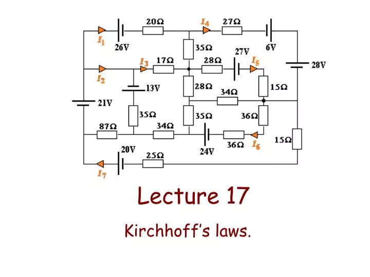
Lecture 17. Kirchhoff’ s laws. . Kirchhoff ’ s laws. Junction rule or KCL (Kirchhoff ’ s current law): The algebraic sum of currents entering a junction must be equal to the algebraic sum of currents leaving the junction. Loop rule or KVL (Kirchhoff ’ s voltage law):

E N D
Lecture 17 Kirchhoff’s laws.
Kirchhoff’s laws Junction rule or KCL (Kirchhoff’s current law): The algebraic sum of currents entering a junction must be equal to the algebraic sum of currents leaving the junction. Loop rule or KVL (Kirchhoff’s voltage law): The algebraic sum of changes in potential in any closed circuit loop must equal zero.
EXAMPLE: Two-loop circuit Determine the currents through the elements of this circuit. ε2 R1 ε1 R2 R3
3 I2 I3 I1 Step 1: How many distinct currents are there? We will need 3 equations Draw them! ε2 R1 ε1 R2 R3
N = 2 Write N - 1 junction equations I2 + I3 = I1 Step 2: How many junctions? ε2 R1 ε1 R2 R3 I2 I3 I1
Many possible loops. In this case we only need 2 of them. Step 3: Draw as many loops as you need to complete the number of required equations (found in step 1) ε2 R1 ε1 R2 R3 I2 I3 I1
Step 4: Write the loop equations for each chosen loop ε1 – I1R1 – I2R2 = 0 ε2 R1 ε1 R2 R3 I2 I3 I1
Path and current in opposite direction ε2 – I2R2 + I3R3 = 0 ε2 R1 ε1 R2 R3 I2 I3 I1
Path is “against” the battery (moving from – to + ends) We only need two of equations, but let us do a third one just for fun… ε1 – I1R1 - ε2 – I3R3 = 0 ε2 R1 ε1 R2 R3 I2 I3 I1
ε1 = 12 V ε2 = 24 V R1 = 5 Ω R2 = 3 Ω R3 = 4 Ω I1 = 0.25 A I2 = 3.6 A I3 = –3.3 A For I3 flows opposite to our assumption Solve the system: 3 eqns, 3 unknowns I2 + I3 = I1 ε1 – I1R1 – I2R2 = 0 ε2 – I2R2 + I3R3 = 0 Nice circuit animations (very visual): http://phet.colorado.edu/web-pages/simulations-base.html