Download
1 / 36
360 likes | 362 Vues
This update provides information on the recent progress, challenges, and modifications made to the spectrometer solenoid magnet for the MICE Cooling Channel. It includes details on magnet cooldown, training, thermal modeling, and the status of Magnet 1 and Magnet 2.

E N D
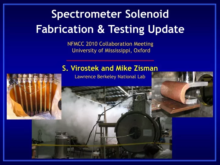
Spectrometer Solenoid Fabrication & Testing Update NFMCC 2010 Collaboration Meeting University of Mississippi, Oxford S. Virostek and Mike Zisman Lawrence Berkeley National Lab
MICE Cooling Channel Layout Spectrometer Solenoid #1 (reassembly under way) Spectrometer Solenoid #2 (modified & ready to cool down)
Topics • Recent magnet cool down and training • HTS lead burn out • Technical review • Current status of Magnet 2 • Thermal modeling and measurements • Magnet 1 progress • Upcoming task schedule
Magnet Status Summary • Magnet 1 was completed in 2008, and training had begun • Ice blockages in LHe recondensing system piping prevented proper operation • Magnet 2 assembly proceeded with design improvements (improved recondensing system, added cold mass venting, better shield connection, precise mechanical alignment) • Magnet 2 became the first unit & Magnet 1 was disassembled • Training of completed Magnet 2 was carried out during 2009 • An HTS lead burned out at 90% of design current due to inadequate cooling • With repairs complete, cool down of Magnet 2 to start soon
Magnet Cooldown Transfer line for LHe cooldown (FNAL contribution) 500 liter LHe dewar
Magnet 2 Testing Results • A leak was found in one of the cold mass vent lines during initial cooldown and was repaired in June ’09 • The subsequent cooldown was successfully completed in only ~3 days w/o incident • However, the shield temperature fell slowly to only about ~115 K at the ends of the cylinder, resulting in added heat flow into the cold mass via the cold mass supports • After filling, the coolers are expected to hold the LHe level, but ~1% of the LHe was boiling off overnight (unpowered) • Training began and was going well with five training quenches at currents ranging from 182 to 238 A
Magnet 2 Testing Results (cont’d) • At 238 A (w/all coils in series), one of the HTS leads burned out due to a higher than allowable temp. at its upper end • The upper lead temperature without current was ~80 K, increasing to >90 K with current, eventually resulting in failure of the lead farthest from the coolers • The lead problem was a surprise, as it was not noticed in the earlier Magnet 1 tests; the feedthroughs and all the leads are the same ones used before in Magnet 1 • The Magnet 2 turret was disassembled to access leads • We are currently thermally testing the feedthroughs and leads in an off line test to see what can be learned
Magnet 2 Burned Out HTS Lead Burned out 500 A lead
MICE Internal Technical Review • Spectrometer Solenoid technical review was held on November 18-19, 2009 at LBNL • Review committee: Pasquale Fabbricatore (chair), Amalia Ballarino, Elwyn Baynham, Tom Bradshaw, Mike Courthold, and Chris White; Alain Blondel and Andy Nichols (ex officio) • The committee came up with several recommendations including the following: - Approved the adding of a single stage cooler to Magnet 2 - Recommended additional thermal modeling of the system - Advised installing additional magnet instrumentation - Suggested Magnet 2 test results be used to determine the final modifications to Magnet 1
Magnet 2 Repair and Modification • A modification to Magnet 2 was proposed that adds a single-stage cryocooler to provide additional cooling to the HTS leads and does not require full magnet disassembly • The plan to add a single-stage Cryomech AL330 cooler (arrived 11/13/09) provides 170 W at 55 K and requires modifications only in the “turret” area • The added cooling power should lower the HTS lead temperature sufficiently to train to full current • The new cooler could remove enough heat to permit the other 3 two-stage coolers to maintain the cold mass LHe level (i.e. closed system)
Original Magnet 2 Configuration Cold head 1st stage HTS leads Fill & vent lines Radiation shield Cold mass
Magnet 2 with Added Cryocooler Single-stage cooler Thermal link HTS leads
Modification Details Added turret space Access port
Current Status of Magnet 2 • The Magnet 2 turret area has been disassembled and modified to allow installation of the single stage cooler • New HTS leads are being installed that have been tested in an off-line apparatus • Additional temperature sensors on the cold heads and voltage taps on the lower HTS leads have been added • Initial pumpdown and leak check of the magnet insulating vacuum is expected during the week of January 18 • Cooldown for testing and training will follow
Magnet 2 Single Stage Cooler Single stage cooler and flexible copper thermal link during fit check in Magnet 2
Future HTS Lead Protection The HTS leads can be actively protected from burnout due to quench as follows: i) Interlock the power supply with the temperature of the top of the HTS leads/heat sink to disable power supply when the temperature is too high ii) Active quench protection based on the voltage across the HTS leads in case of resistive transition (~3 mV limit); voltage taps have been added to the lower end of the leads Both of these systems could be implemented in the RAL control system after magnet delivery
Our modeling indicates the new cooler won’t substantially affect the shield temperature It is uncertain whether the addition of the single-stage cooler will solve the LHe boil off issue Cannot address known deficiencies in Magnet 2 (shield connection, copper plate thickness, leads arrangement) without fully disassembling magnet Additional cooler(s) will increase utility costs for running the magnets (water and power) Other Issues
Magnet 2 Fallback Scenario • If the addition of a single-stage cooler to Magnet 2 does not result in a closed system, there are two options: • i) Accept the thermal properties as is and top up the magnet with external cryogens as needed • ii) Disassemble and modify the magnet to improve the shield connections and to accommodate a fourth two-stage cooler (in addition to the single-stage cooler) • The 2nd option would add ~6 months to the delivery of the 2nd magnet to RAL and create additional risks of damage or assembly errors in the repair process • For these reasons, the first option is preferred
Thermal Calculations and Measurements • A thermal model of the magnet was developed and is being used to understand the cooling mechanisms and heat loads • Initial calculations indicate the upper HTS leads temp. will be <70K during operation w/the added cooler • The temperature drop across the thermal link between the single stage cooler and the 1st stage copper plate is expected to be ~10 K • An off-line magnet lead test is being carried out by Wang NMR to measure all relevant temperatures and voltages during operation • Additional sensors will directly measure cold head temps.
Thermal Shield Model • FEA model of thermal shield, 1st stage plate and HTS leads • Proposed magnet modifications are also being modeled
Magnet Lead Test Thermal connection 1st stage plate HTS lead
Initial Test Results (1) Tests began on January 14, 2010 at initial equilibrium (no current), leads gave ~10 W heat load into cooler stage 1 temperature at top of leads was below freezing cooler temperatures: 33.8 K (stage 1); 3.5 K (stage 2) next, powered leads to 275 A voltage drops on leads were 99 and 95 mV, respectively means about 27 W per lead…unexpectedly high leads too long for their cross-sectional area temperature at top of leads was 350 K (hot!) cooler temperatures: 42.4 K (stage 1); 3.5 K (stage 2)
Initial Test Results (2) Added 20 W to shield (stage 1 load) with 275 A in leads results: cooler temperatures: 56 K (stage 1); 3.9 K (stage 2) lead voltage drops increased to 104 and 101 mV, respectively because leads now running hotter than before T between stage 1 and copper plate (across plug-in joint): 1.1 K at 33.8 K, 2.4 K at 42.4 K, and 1.4 K at 56 K grease probably more conductive at higher temperature means that “plug-in” aspect working as expected Next, will increase cross section and decrease L of leads then retest next week
Magnet 1 Plans implement ideas to improve thermal connection between coolers and shield and lower cold mass support intercept temperature use copper sheets rather than Al cylinder use Al-1100 strips on outside of shield to improve heat conductivity make preparations for using additional 2-stage cooler augmenting the single-stage cooler to solve both thermal problems decision to add 5th cooler depends on outcome of Magnet 2 tests modify cold mass fill pipe to facilitate clearing a blockage should one occur
Magnet 1 Cold Mass Added port for possible 4th 2-stage cooler
Magnet 1 Shield Corresponding hole for 4th 2-stage cooler added to shield shield is also being “beefed up” locally to improve heat transfer to edges this is where cold-mass support intermediate temperature point is connected extra heat load from higher temperature at this point is burden for stage 2 of coolers probably more of an issue than bulk radiation load New connection for cooler added Area where cold-mass support intercept attached Attachment point for LN2 reservoir
Heat Shield Thermal Connections Previous attempt to improve thermal connection between stage 1 of coolers and shield was a failure aluminum bands were even worse than original copper strips next iteration will make connections between stage 1 copper plates and shield with thick copper sheets
2-Stage Cooler Modification A fourth 2-stage cooler could be added as shown below still leaves room for the single-stage cooler Side view: Top view:
Magnet 1 Issues Need to determine whether we need fourth 2-stage cooler to maintain cryogen level the single-stage cooler for Magnet 1 is on order Possible that improvements to the shield connection, along with the single-stage cooler, will suffice if it works on magnet 2, the answer is clear if it “almost” works, the answer is not so clear We can answer the questions “sequentially”, but each trial costs time and money Present approach requires one additional cooler per magnet, and maybe two
Schedule Overview * These step are only required if the initial modifications to Magnet 2 are unsuccessful
Coupling Coil Status Coupling coil design essentially finished still working to get complete and consistent set of drawings LBNL (DeMello) will assist in this Coil fabrication job out for bid expect responses in February, aim to sign contract in March for all three coils HIT may not have enough funds for entire job may need additional U.S. contribution New management structure in place at HIT Li Wang, Chief Engineer; FengYu Xu, Project Manager contract in place with IHEP consultants (technical experts) D. Li, S. Virostek, A. DeMello, M. Green are key players
A fix to Magnet 2 has been implemented which did not require full magnet disassembly Addition of a single-stage cooler to the first stage copper plate is expected to solve the HTS leads temperature problem Temperature of the thermal shield may still be an issue (cooler will have minimal impact) Operation without the need for cryogen top off is not guaranteed Magnet 2 test results will be used to assess the degree of modification required for Magnet 1 Summary