Download
1 / 15
150 likes | 201 Vues
Orthographic Projection. Sectional Views. Section Views.

E N D
Orthographic Projection Sectional Views
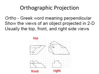
Section Views • When a part has a lot of interior details, hidden lines can make the part hard to understand and dimension. To see the interior of these parts, we cut some of the part away. This allows for details to be seen clearly, as well as, giving us alternative locations to properly dimension the part.
Sectional Views • Types of Sectional Views • Half • Full • Offset • Removed • Revolved • Broken-out • Aligned
In a half section, one quarter of the part is cut away. This is done with symmetrical parts where you would like to show the outside, as well as, the inside details. Half Section Notice how the cutting plane line runs through the center of the part and there is no arrow head.
Full Section A full section is a view that shows what the object looks like if it were cut in half. A cutting plane line is used to indicate how the front view was cut. It is also labeled in case another section is necessary. The arrows should point in the line of sight as you are looking straight on at the section. Section lines called Hatch lines are used to show where the part is solid. This helps to see the detail that would be normally blocked and only shown as hidden lines.
Offset Section Interior features not in line with each other can be shown in an offset section view. Note how the cutting plane line changes and follows the center of each feature.
Revolved Sections • Used when an object has a constant shape throughout the length that cannot be illustrated in an external view. • The section is revolved 90 degrees. It may be represented one of two ways, either broken away or not.
Not Broken Away Revolved Section Section is revolved 90 degrees
Broken Away Revolved Section Section is revolved 90 degrees and broken away from part
Broken-out Section Views • A small portion of an object may be broken away to clarify an interior surface or feature. No cutting plane line is used.
Broken-out Section View Section exposes the interior surfaces
Removed Sections • A cutting plane is placed through the part where the section is taken. The removed sections are not aligned with the view. Placement is in the surrounding area.
Sections are not aligned with the view. Removed Sections
Aligned Section Views • A true projection of a part with inclined ribs, spokes, and arms will be foreshortened. An aligned section view is recommended to acquire accurate dimensions of the part. The cutting plane is bent at an angle as it passes through the object. The section view is then projected 90 degrees from the cutting plane and is in alignment to the original view.
View is projected 90 degrees from the cutting plane and is in alignment to the original view. Cutting plane is bent at an angle Aligned Section Views