Download
1 / 36
360 likes | 552 Vues
Global Heart and Vascular Institute Kaleida Health and the University at Buffalo. William McDevitt Structural Option AE 482 – Senior Thesis Dr. Richard Behr. Cannon Design. Cannon Design. Presentation Outline. Introduction Existing Structural System Thesis Proposal Structural Depth

E N D
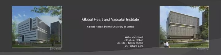
Global Heart and Vascular Institute Kaleida Health and the University at Buffalo William McDevitt Structural Option AE 482 – Senior Thesis Dr. Richard Behr Cannon Design Cannon Design
Presentation Outline Introduction Existing Structural System Thesis Proposal Structural Depth Construction Management Breadth Conclusion Cannon Design Cannon Design
Introduction Presentation Outline Introduction Building Information Primary Project Team Existing Structural System Thesis Proposal Structural Depth Construction Management Breadth Conclusion Building Information 10-story medical facility Located in Buffalo, NY 476,500 sf $291 million Construction Dates: February 2008 – April 2011 Primary Project Team Owner(s): Kaleida Health & Buffalo 2020 Development Corporation Architect and Engineers: Cannon Design Construction Manager/General Contractor: Turner Construction Cannon Design
Existing Structural System Presentation Outline Introduction Existing Structural System Foundation Gravity System Lateral System Thesis Proposal Structural Depth Construction Management Breadth Conclusion Foundation Grade beams and pile caps - 4000 psi concrete Steel helical piles - HP12x74 sections - Allowable axial capacity of 342 kips - Driven to refusal on limestone bedrock 5” Slab on grade Cannon Design
Existing Structural System Presentation Outline Introduction Existing Structural System Foundation Gravity System Lateral System Thesis Proposal Structural Depth Construction Management Breadth Conclusion Gravity System Floor System - 3” Composite Metal Deck - Total slab thickness ranging from 4” to 7 ½” - 18-gage galvanized steel sheets Columns - W14 shapes, ranging from 68 to 370 lb/ft - Spliced every 36’ - Provides 18’ floor-to-floor height Universal Grid Layout - Bay size of 31’-6” by 31’-6” - Beams spaced at 10’-6” Cannon Design
Existing Structural System Presentation Outline Introduction Existing Structural System Foundation Gravity System Lateral System Thesis Proposal Structural Depth Construction Management Breadth Conclusion Lateral System Concentrically braced frames around the perimeter All HSS sections Low cost compared to moment frames Cannon Design
Existing Structural System Presentation Outline Introduction Existing Structural System Foundation Gravity System Lateral System Thesis Proposal Structural Depth Construction Management Breadth Conclusion Lateral System Concentrically braced frames around the perimeter All HSS sections Low cost compared to moment frames
Thesis Proposal Presentation Outline Introduction Existing Structural System Thesis Proposal Structural Depth Construction Management Breadth Mechanical Breadth MAE Requirements Structural Depth Construction Management Breadth Conclusion Structural Depth Concrete system could be less expensive Explore three alternatives discussed in Tech 2 - Flat slab with drop panels - One-way joist and beam - Pre-cast hollow core plank Redesign gravity and lateral systems Perform vibration analysis Goal is to design a more cost effective solution
Thesis Proposal Presentation Outline Introduction Existing Structural System Thesis Proposal Structural Depth Construction Management Breadth Mechanical Breadth MAE Requirements Structural Depth Construction Management Breadth Conclusion Construction Management Breadth Detailed Cost Analysis - Current steel structure - Redesigned concrete structure Schedule Analysis - Current steel structure - Redesigned concrete structure Determine if redesign is more cost effective
Thesis Proposal Presentation Outline Introduction Existing Structural System Thesis Proposal Structural Depth Construction Management Breadth Mechanical Breadth MAE Requirements Structural Depth Construction Management Breadth Conclusion Mechanical Breadth Building envelope and façade study - Obtain current curtain walls designs - Research more efficient glazing system - Perform thermal calculations using Trace 700 - Compare various alternatives
Thesis Proposal Presentation Outline Introduction Existing Structural System Thesis Proposal Structural Depth Construction Management Breadth Mechanical Breadth MAE Requirements Structural Depth Construction Management Breadth Conclusion Mechanical Breadth Building envelope and façade study - Obtain current curtain walls designs - Research more efficient glazing system - Perform thermal calculations using Trace 700 - Compare various alternatives MAE Requirements RAM Structural System, ETABS, and SAP2000 models will utilize information learned in AE 597A, Computer Modeling of Building Structures Mechanical Breadth will reference content from AE 542, Building Enclosure Science and Design Vibration analysis will constitute MAE level work
Structural Depth Presentation Outline Introduction Existing Structural System Thesis Proposal Structural Depth Gravity System Redesign Lateral System Redesign Vibration Analysis Construction Management Breadth Conclusion Gravity System Redesign Explored three alternative systems - Flat slab with drop panels - One-way joist and beam - Pre-cast hollow core plank Flat slab with drop panel system chosen - Lowest cost - Utilize current bay size - Relatively flat ceiling Designed gravity columns Gravity Loads Floor System Dead Loads - Concrete self-weight - Superimposed Dead Load = 25 psf Floor System Live Loads - Conservatively assumed 125 psf for all floors Snow Load Ground snow load determined from a case study to be 50 psf by Cannon Design Calculated flat roof snow load of 42 psf
Structural Depth Presentation Outline Introduction Existing Structural System Thesis Proposal Structural Depth Gravity System Redesign Lateral System Redesign Vibration Analysis Construction Management Breadth Conclusion Flat Slab Design Performed hand calculations - Minimum slab thickness of 11” per ACI 9.5.3.2 - 10 ½’ by 10 ½’ drop panels - 3 ½”depth Modeled in spSlab - Three alternatives for drop panel depth - Chose 3 ½” depth with 6000 psi concrete Determined column and middle strip reinforcement - Used #7 bars for top and bottom reinforcement Interior Bays Exterior Bays
Structural Depth Presentation Outline Introduction Existing Structural System Thesis Proposal Structural Depth Gravity System Redesign Lateral System Redesign Vibration Analysis Construction Management Breadth Conclusion Column Design Approximated sizes using RAM Structural System - Ranged from 20” by 20” to 36” by 36” - Unbraced length controlled the column size Summed axial loads on a corner, exterior, and interior column Determined column was part of a nonsway frame Checked slenderness Designed sub-basement, interior column by hand Checked hand design using spColumn Proceeded with design using spColumn
Structural Depth Presentation Outline Introduction Existing Structural System Thesis Proposal Structural Depth Gravity System Redesign Lateral System Redesign Vibration Analysis Construction Management Breadth Conclusion Column Design Approximated sizes using RAM Structural System - Ranged from 20” by 20” to 36” by 36” - Unbraced length controlled the column size Summed axial loads on a corner, exterior, and interior column Determined column was part of a nonsway frame Checked slenderness Designed sub-basement, interior column by hand Checked hand design using spColumn Proceeded with design using spColumn
Structural Depth Presentation Outline Introduction Existing Structural System Thesis Proposal Structural Depth Gravity System Redesign Lateral System Redesign Vibration Analysis Construction Management Breadth Conclusion Lateral System Redesign Determined wind and seismic loads Found controlling load combination Designed shear walls Checked drift limitations Checked relative stiffness assumption Examined overturning and foundation impact
Structural Depth Presentation Outline Introduction Existing Structural System Thesis Proposal Structural Depth Gravity System Redesign Lateral System Redesign Vibration Analysis Construction Management Breadth Conclusion Wind Loads Chapters 26 and 27 of ASCE 7-10 Occupancy category – IV - 120 mph basic wind speed Explored four wind cases - Case 1 controls Total base shear - East-West direction = 1581.7 kips - North-South direction = 1535.5 kips Figure 27.4-8 from ASCE 7-10
Structural Depth Presentation Outline Introduction Existing Structural System Thesis Proposal Structural Depth Gravity System Redesign Lateral System Redesign Vibration Analysis Construction Management Breadth Conclusion Wind Loads Chapters 26 and 27 of ASCE 7-10 Occupancy category – IV - 120 mph basic wind speed Explored four wind cases - Case 1 controls Total base shear - East-West direction = 1581.7 kips - North-South direction = 1535.5 kips
Structural Depth Presentation Outline Introduction Existing Structural System Thesis Proposal Structural Depth Gravity System Redesign Lateral System Redesign Vibration Analysis Construction Management Breadth Conclusion Wind Loads Chapters 26 and 27 of ASCE 7-10 Occupancy category – IV - 120 mph basic wind speed Explored four wind cases - Case 1 controls Total base shear - East-West direction = 1581.7 kips - North-South direction = 1535.5 kips
Structural Depth Presentation Outline Introduction Existing Structural System Thesis Proposal Structural Depth Gravity System Redesign Lateral System Redesign Vibration Analysis Construction Management Breadth Conclusion Seismic Loads Chapters 11 and 12 of ASCE 7-10 Assumed both directions would be the same Estimated total building weight of 86240 kips Equivalent Lateral Force Procedure - Seismic design category C - R = 5.0 - Base shear of 1380 kips
Structural Depth Presentation Outline Introduction Existing Structural System Thesis Proposal Structural Depth Gravity System Redesign Lateral System Redesign Vibration Analysis Construction Management Breadth Conclusion Load Combinations 1) 1.4D 2) 1.2D + 1.6L + 0.5(Lr or S or R) 3) 1.2D + 1.6(Lr or S or R) + L 4) 1.2D + 1.6(Lr or S or R) + 0.5Wx 5) 1.2D + 1.6(Lr or S or R) + 0.5Wy 6) 1.2D + 1.0Wx + L + 0.5(Lr or S or R) 7) 1.2D + 1.0Wy + L + 0.5(Lr or S or R) 8) 1.2D + 1.0Ex + L + 0.2S 9) 1.2D + 1.0Ey + L + 0.2S 10) 0.9D + 1.0Wx 11) 0.9D + 1.0Wy 12) 0.9D + 1.0Ex 13) 0.9D + 1.0Ey
Structural Depth Presentation Outline Introduction Existing Structural System Thesis Proposal Structural Depth Gravity System Redesign Lateral System Redesign Vibration Analysis Construction Management Breadth Conclusion Load Combinations 1) 1.4D 2) 1.2D + 1.6L + 0.5(Lr or S or R) 3) 1.2D + 1.6(Lr or S or R) + L 4) 1.2D + 1.6(Lr or S or R) + 0.5Wx 5) 1.2D + 1.6(Lr or S or R) + 0.5Wy 6) 1.2D + 1.0Wx + L + 0.5(Lr or S or R) 7) 1.2D + 1.0Wy + L + 0.5(Lr or S or R) 8) 1.2D + 1.0Ex + L + 0.2S 9) 1.2D + 1.0Ey + L + 0.2S 10) 0.9D + 1.0Wx 11) 0.9D + 1.0Wy 12) 0.9D + 1.0Ex 13) 0.9D + 1.0Ey
Structural Depth Presentation Outline Introduction Existing Structural System Thesis Proposal Structural Depth Gravity System Redesign Lateral System Redesign Vibration Analysis Construction Management Breadth Conclusion Shear Wall Design Placed two 16” thick shear walls in each direction Located on the perimeter Assumed each would take 50% of the load applied in that direction Used ETABS to determine the wall with the largest base shear Designed all four walls , by hand, for this controlling shear value - 16” thick wall - #4 bars at 10” for horizontal reinforcement - #4 bars at 10” for vertical reinforcement - (10) #9 bars at 2” for flexural reinforcement
Structural Depth Presentation Outline Introduction Existing Structural System Thesis Proposal Structural Depth Gravity System Redesign Lateral System Redesign Vibration Analysis Construction Management Breadth Conclusion Drift Analysis Checked controlling seismic load combination for story drift - 0.010hsx (Table 12.12-1 in ASCE 7-10) Checked controlling wind load combination for total building drift - H/400 All drift values were acceptable
Structural Depth Presentation Outline Introduction Existing Structural System Thesis Proposal Structural Depth Gravity System Redesign Lateral System Redesign Vibration Analysis Construction Management Breadth Conclusion Relative Stiffness Check Reasonable method for checking the assumed distribution of lateral load Placed 100 kip load at the top of each wall Measured lateral displacement in inches Calculated relative stiffness of both shear walls in either direction
Structural Depth Presentation Outline Introduction Existing Structural System Thesis Proposal Structural Depth Gravity System Redesign Lateral System Redesign Vibration Analysis Construction Management Breadth Conclusion Vibration Analysis Current Design - Moderate walking pace of 75 steps/minute - Velocities ranging from 4000 – 500 µ in/sec Checked redesign to determine if criteria was met Built 3-bay by 3-bay SAP2000 model - Slab modeled as 11” shell element - Drop panels modeled as 14 ½” shell elements - Discretized each into 9” by 9” squares - Columns modeled halfway above and below - Assumptions: E = 1.2Ec I = 0.7Ig for columns I = 0.25Ig for slab and drops
Structural Depth Presentation Outline Introduction Existing Structural System Thesis Proposal Structural Depth Gravity System Redesign Lateral System Redesign Vibration Analysis Construction Management Breadth Conclusion Vibration Analysis Separately placed 1 kip load at the center of interior and exterior bay Measures deflection in inches Determined fundamental period and natural frequency Mode 7 Shape for Exterior Bay
Structural Depth Presentation Outline Introduction Existing Structural System Thesis Proposal Structural Depth Gravity System Redesign Lateral System Redesign Vibration Analysis Construction Management Breadth Conclusion Vibration Analysis Separately placed 1 kip load at the center of interior and exterior bay Measures deflection in inches Determined fundamental period and natural frequency Mode 11 Shape for Interior Bay
Structural Depth Presentation Outline Introduction Existing Structural System Thesis Proposal Structural Depth Gravity System Redesign Lateral System Redesign Vibration Analysis Construction Management Breadth Conclusion Vibration Analysis Calculated the vibrational velocity for each bay Uv = 5500 lb Hz2 (moderate walking) Interior Bay = 2918 µ in/sec Exterior Bay = 3929 µ in/sec Potential Improvements - Increase concrete strength - Increase slab thickness - Decrease span length Required Vibrational Velocities 4000 µ in/sec - Typical lab and surgery areas 2000 µ in/sec - Laboratory areas near corridors 1000 µ in/sec - Central lab areas with sensitive photography equipment 500 µ in/sec - Extremely sensitive areas
Construction Management Breadth Presentation Outline Introduction Existing Structural System Thesis Proposal Structural Depth Construction Management Breadth Detailed Cost Analysis Schedule Analysis Conclusion Detailed Cost Analysis Estimated the current steel building cost to create a relevant baseline - Used RSMeans Building Construction Cost Data - About $11.9 million Estimated concrete structure - Used RSMeans Building Construction Cost Data - About $11.6 million About $300,000 savings, or 2.9% cost reduction Steel Construction Cost
Construction Management Breadth Presentation Outline Introduction Existing Structural System Thesis Proposal Structural Depth Construction Management Breadth Detailed Cost Analysis Schedule Analysis Conclusion Detailed Cost Analysis Estimated the current steel building cost to create a relevant baseline - Used RSMeans Building Construction Cost Data - About $11.9 million Estimated concrete structure - Used RSMeans Building Construction Cost Data - About $11.6 million About $300,000 savings, or 2.9% cost reduction Concrete Construction Cost
Construction Management Breadth Presentation Outline Introduction Existing Structural System Thesis Proposal Structural Depth Construction Management Breadth Detailed Cost Analysis Schedule Analysis Conclusion Schedule Analysis Determine which system results in a longer construction time Examined schematic design schedule for steel building that was obtained from Cannon Design - 192 days, or about 9 months Assembled concrete structure schedule - RSMeans daily output values - Projects of comparable size - 242 days, or about 11 months Steel Construction Schedule
Construction Management Breadth Presentation Outline Introduction Existing Structural System Thesis Proposal Structural Depth Construction Management Breadth Detailed Cost Analysis Schedule Analysis Conclusion Schedule Analysis Determine which system results in a longer construction time Examined schematic design schedule for steel building that was obtained from Cannon Design - 192 days, or about 9 months Assembled concrete structure schedule - RSMeans daily output values - Projects of comparable size - 242 days, or about 11 months Concrete Construction Schedule
Conclusion Presentation Outline Introduction Existing Structural System Thesis Proposal Structural Depth Construction Management Breadth Conclusion The main goal of this thesis was to design a concrete building in the hope that it would be less expensive than its steel counterpart While the concrete building is currently about $300,000 less expensive, several factors should be considered Inadequate vibration design Foundation strengthening Cold weather concreting in Buffalo, NY Elongated schedule In the end, the current steel building is probably the more efficient and economical design
Acknowledgements Presentation Outline Introduction Existing Structural System Thesis Proposal Structural Depth Construction Management Breadth Conclusion Cannon Design Rachel Chicchi Chip Barry Kaleida Health Mickey Mariacher Penn State AE Faculty and Staff Dr. Richard Behr – Faulty Advisor Dr. Linda Hanagan Professor Kevin Parfitt Professor Robert Holland My family and friends!
Questions and Comments? Cannon Design Cannon Design