Download

1 / 113
1.16k likes | 1.42k Vues
SYNCHRONOUS DIGITAL HIERARCHY. What is Synchronous Transmission.

E N D
What is Synchronous Transmission • Synchronous Transmission has been developed to overcome the problems associated with Plesichronous Transmission, in particular the inability of the PDH to extract individual circuits from high capacity systems without having to demultiplex the whole system.
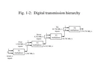
Main Feature of SDH • Network Management Capability • Channel Extraction • Any existing PDH Transmission Rate to be packaged into an STM-1 frame.
Principles of SDH • SDH DIAGRAM
SDH Priniciples • The SDH defines a number of containers, each corresponding to an existing PDH rate. • Information from PDH signal is mapped into the relevant container. The way in which this is done is similar to bit stuffing procedure carried out in PDH MUX. • Each container then has some control information known as the “path overhead” added to it.
Cont--------- • PATH OVER HEAD bytes allow the network operator to achieve end to end path monitoring of things such as error rates. • Together the container and the path overhead form a “VIRTUAL CONTAINER” FIG
Cont----------- • In a synchronous network, all equipment is synchronized to an over all network clock. • It is important to note that the delay associated with a transmission link may vary slightly with time. As a result the location of virtual containers within STM-1 frame is may not be fixed. • These variations are accommodated by associating a pointer with each VC.
Cont----------- • The pointer indicates the position of the beginning of the VC in relation to the STM-1 frame. • It can be incremented as necessary to a accommodate movements of the position of the VC.
Cont-------- • G.709 defines different combinations of virtual containers which can be used to fill up the payload area of an STM-1 frame. The process of loading containers and attaching overhead is repeated at several levels in SDH, resulting the “nesting” of smaller VCs within larger ones. This process is repeated until the largest size of VC (VC-4 in Europe) is filled, and this is loaded into the pay load of the STM-1
Cont----------- • When the payload area of the STM- 1 frame is full, some more information bytes are added to the frame to form a “Section Overhead” • The section overhead bytes are so-called because they remain with the payload for the fiber section between to SDH MUX.
Purpose of Section Overhead bytes • Their purpose is to provide communication channels for functions such as OA&M facilities. • User channel • Protection switching • Section performance • Frame alignment • Etc.
BYTE INTERLEAVING MULTIPLEXING SCHEME • When a higher transmission rate than the 155 Mbits/s of STM-1 is required in a synchronous network, it is achieved by a relatively straight forward “Byte interleaving Multiplexing scheme” • In this way rates of 622 Mbits/s (STM-4) - 10 Gbits/s (STM-64) can be achieved.
Benefits of Synchronous Network • Network Simplification: A single SDH MUX can perform the function of an entire PDH MUX mountain. • Fig • Leading to significant reduction in the amount of equipment used. Lower operating costs will also result through reduction in spares inventory required, simplified maintenance, and also reduction in floor space required by the equipment, and lower power consumption.
Benefits of Network simplification cont------- • The more efficient “drop and insert” of channels offered by an SDH network, together with its powerful network management capabilities, will lead to greater ease in provisioning of high bandwidth lines of news multimedia services as well as ubiquitous access to those services. • Thus the simplification of the network, and flexibility this brings opens up the potential for network operator to generate new revenue.
Survivability • The deployment of optical fiber throughout the network and adoption of the SDH network element makes end to end monitoring and maintenance of network integrity a possibility. The network management capability of the synchronous network will enable the failure of links or even nodes to be identified immediately. Using self healing ring architecture, the network will be automatically reconfigured with traffic intensity rerouted until such a time as the faulty equipment has been repaired.
Survivability cont----- • Thus, failure in the network transport mechanism will be invisible on an end to end basis. Such failure will not disrupt services, allowing network operators to commit to extremely high availability of service figures and guarantee high levels of network performance
Software Control • Provision of network management channels within the SDH frame structure means that a synchronous network will be fully software controllable. Network management system will not only perform traditional event management functions- dealing with alarms in the network, but will also provide a host of other functions, such as performance monitoring, configuration management, resource management Network Security, Inventory Management and Network Planning and design.
Software Control cont------- • The possibility of remote provisioning and centralized maintenance will mean a great saving in time spent by maintenance personnel in traveling to remote sites, and this of course corresponds to expense saving.
Bandwidth on Demand • In a synchronous network it will be possible to dynamically allocate network capability, or bandwidth, on demand. User any where within the network will be able to subscribe at very short notice to any service offered over the network, some of which may require large amount of bandwidth. An example of this is dialup video conferencing. User link just by dialing the appropriate number, as opposed to the current situation where videoconferencing link must be booked days in advance.
Bandwidth on demand Cont--- • Many other new services become possible in a synchronous network. These will represent new source of revenue for network operators, and increased convenience for users. Some examples are high speed packet services, LAN interconnection and HDTV
Future Proof Networking • The synchronous Digital Hierarchy offers network operators a future proof network solution, plus software upgradeability and extensions to existing equipment.
ELEMENTS of SYNCHRONOUS TRANSMISSION SYSTEM • Multiplexers: Synchronous Multiplexers, as defined by ITU-T SDH recommendations, perform both multiplexing and line terminating functions, as shown in • Fig • Thus a synchronous MUX replaces a bank of PDH and associated line terminating equipment, while at the same time bringing new functionality.
SDH MUX cont--------- • Synchronous Multiplexers can accept a wide range of tributaries, and offer a number of possible output data rate as shown in • Fig • On the tributary side, all current PDH bit rates can be accommodated.
SDH MUX cont---------------- • The synchronous Optical Interface of the synchronous multiplexer can be duplicated for protection. This can be done in two ways, either traditional 1+1 protection can be provided, or the optical port can operate in an EAST/ WEST NODE to allow the implementation of ring topologies. • Synchronous ring can improve resilience and reduce both fiber requirement and network cost.
Point to Point Configurations • Synchronous Multiplexers can be used effectively high capacity point to point applications where they are cost competitive with PDH solutions. The equipment facilitates provision of new services and provide an upgrade path as network evolves. • fig
ADD DROP CONFIGURATION • This configuration is similar to the previous one but the fact that a number of MUX are used to provide connectivity between nodes along a route. The MUX are configured to add drop channel at these node
RING CONFIGURATION • For areas of the network requiring high survivability, synchronous multiplexers may be configured as a high capacity “self healing” fiber ring. The ring structure is able to reconfigure without the intervention of external network management should equipment or cable occur maintaining continuity of service
By using tributary interfaces, a terminal can be configured as a fiber hub for use in multi-site network applications, This eliminates the need for back fiber terminals. In addition to its operation capabilities, a synchronous multiplexer offer a Network Management channel which may provide alarm and monitoring information for individual tributaries within an STM-1 signal HUB CONFIGURATIONS
HUB CONFIGURATION CONT--- • Not only does this provide enhanced management abilities, but since management within the SDH is to be standardized, additional cost benefits can be realized by network Operator through more efficient Management System.
CROSS CONNECT FUNCTIONALITY • Cross Connections in a synchronous network involves setting up semi-permanent interconnections between different channels, enabling routing to be performed down to a VC level. • This description seems to suggest that cross connection is similar to switching, but there are fundamental difference between two .
Cross Connect CONT------ • The main difference is that a switch operates as a temporary connection which is set up under the control of the end user, while cross connection is a transmission technique use to set up a semi permanent connection under the control of the network operator via a network manager. • However, as network services evolves to wideband and broadband, it is certainly possible that the switch and cross connect functions will begin to merge. This is particularly true when ATM services begin volume deployment
Cross Connect Cont------ • There is also a distinction between the plesiochronous cross connect unit which has established itself to some extent within current networks, and the synchronous cross connection function. • The traditional PDH X-connect was developed to replace manual digital distribution frames which were seen as reliable and labor intensive as shown in • Fig • Slow to setup, prone to error and expensive.
X-CONNECT CONT------- • In deploying a plesiochronous automatic Digital Distribution Frame, this allows traffic passing through the cross connect to effectively share the physical connection at different instances in time. However this requires that all traffic through a PDH X-Connect is synchronized, thus necessitating the expense of providing a justifications mechanism at the interface between it and the network.
X-CONNET CONT----- • The traffic rates through plesiochronous cross connect also need to be limited to a manageable size since these cross connect can only easily operate at a single rate. Most choose to switch at the 64 Kbits/s level and interface at 2 Mbit/s. This means that all traffic must be demultiplexed to 2 Mbits/s before it can be connected, thus increasing equipment requirement, sized and cost.
X-Connect Cont--- • With the introduction of synchronous transmission system the need for any justification of signals at the interface with the cross connecting device is removed. Fig shows the difference between PDH and SDH X-Connect. • Probably the most important difference between the plesiochronous network digital cross-connect (referred the plesiochronous network digital cross connect (refered as DXC) and the synchronous cross connect function is the actual deployment planning.
Cont--- • A DXC is required wherever a large add-drop function is performed or where a lot of manual reconfiguration takes place in the network to provide new service or groom existing service for efficient facility utilization. • Any of these application required the use of a distinct piece of plesiochronous equipment called a DXC to perform the function.
DXX Cont--- • The synchronous X-Connect function, when required does not necessarily mean the need for a separate piece of equipment. The flexibility of SDH allows the cross connect functionality to reside in almost any network element, the most obvious being an add-drop MUX.
SDXC (Synchronous Digital X-Connet) • There are two types of dedicated SDXC commonly referred to, the • SDXC 4/4. • SDXC 4/1 • These are used in special applications to supplement the distributed cross-connect functionality of a synchronous network. The numbering scheme describe the VC level at which they can accept inputs and cross-connect respectively. It can be seen that the difference between the two is the multiplex level at which they can cross connect traffic.
SDXC 4/4 • The SDXC 4/4 is usually designed to accept input s at 140, 155 or 622 Mbits/s or higher. It can cross-connect at 155 or 140 Mbits/s. It may be used in the core of the transmission network for network protection as an alternative to STM-16 base protection ring architecture.
SDXC 4/1 • The SDXC 4/1 can usually accept combinations of 2,155 and 622 Mbits/s input. It can cross connect VC-1 containers, i.e 2Mb/s channels, though in many cases 4/1 cross connects will also be able to cross connect VC-2s, concatenated VC-2s, VC-3, and VC-4. These pieces of equipment may be used where special circumstances lead to the requirement for a point of additional flexibility in the outer core transmission network.
SYNCHRONOUS DEPLOYMENT • Multi-vendor Connectivity • Technological Discontinuity. • Reduction in equipment. • Improved Network Resilience. • Network Management. • Single Stage Multiplexing. • Single Stage Multiplexing. • Distributed Bandwidth Management. • Software Down load • Ring Deployment.
SDH Deployment • Implementation of New Services. • Improved Earning. • Deployment Triggers • Modernisation • The SDH Solution • Network Evolution • Management Services Network • International Services Network
Multi vendor Connectivity The standardisation of synchronous interfaces means that a planner can mix and match products from different vendors in the network, without having to concerned about their ability to work together. However there is still the possibility of implementing the standards in different ways. Thus the network planner must understand the impact of choosing between such options as, Floating,or Fixed mode mapping, or choosing between asynchronous, bit synchronous or Byte synchronous mapping.
Technological Discontinuity • Because synchronous can carry plesiochronous payload it can be deployed in an evolutionary manner. However, because of the changes associated with synchronous systems it does represent something of a technological discontinuity. Thus, in order to effectively overcome the limitations of the PDH, network operators must plan the introduction of the synchronous into their network with care.
Reduction in Equipment • SDH will lead to simplification of the network. The multiplexing structure allows for greater integration of products, along with greater control of equipment. The network planner faces the exciting challenge of using synchronous equipment in such a way as to unleash the full power inherent in it.
Improved Network Resilience • A synchronous network will be more reliable due to both the increased reliability of individual elements, and the more resilient structure of the whole network. Synchronous will allow development of network topologies which will be able to achieve “network protection” , that is survive failures in the network by reconfiguring and maintaining service by alternate means. Network Protection can be achieved the use of cross connect functionality to achieve restoration or through the use of self-healing ring architectures.
NETWORK MANAGEMENT • SDH gives the network operator the opportunity to manage network performance effectively and make change flexibility as required. Synchronous equipment will have a significant proportion of its design embedded in software instead of hardware. Therefore, the network manager will be able to control equipment configuration changes through software management. What is ultimately required is the ability for the network manager to implement what is called “ IN SERVICE PROVISIONING”.
NETWORK MANAGEMENT ---- • This is where a request for service is entered into the network manager via a terminal or other electronic mean and is then broken down into a series of instructions to each network element involved in that service. Each network element is then configured and provisioned in software to support the service request without having to be taken out of service. It is important that the network operator plans his network in such a way as to take advantage of benefits resulting from “in service provisioning”.
Single Stage Multiplexing • The SDH multiplexing structure allows many different tributaries to be multiplexed together into an STM-n signal in a single stage of multiplexing. Thus the network planner is not bound by a rigidly hierarchical network structure, as he was with the PDH. The planner now has at his disposal the bandwidth flexibility essential for the introduction of new services.
Distributed Bandwidth Management • The plesiochronous cross connect was originally conceived as a devie to sumplify routing and gromming at srtrategic poinit s in the network, However, the necessity to transport traffic to cross connet site often outwidhed the benefirs gained.