Download

1 / 23
250 likes | 490 Vues
Plesiochronous Digital Hierarchy. PDH MULTIPLEXING. PLESIOCHRONOUS HIGHER ORDER DIGITAL MULTIPLEXING. PDH MUX NORTH AMERICA. The 24 channel PCM system is the primary order of Digital MUX.

E N D
PDH MULTIPLEXING • PLESIOCHRONOUS HIGHER ORDER DIGITAL MULTIPLEXING
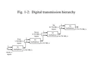
PDH MUX NORTH AMERICA • The 24 channel PCM system is the primary order of Digital MUX. • If it is necessary to transmit more than 24 channels, the system is build-up as in the “Plesiochronous Digital Hierarchy” as shown in the diagram
DIGITAL TRANSMISSION HIERARCHY 1 T4 MUX 274.176 Six 44.736 Mbits/s inputs 6 Mbits/s 1 T3 MUX Seven 6.312 inputs 7 1 Four 1.544Mbits/s Inputs T2 MUX 6.312 Mbits/s 4 TI MUX 1 1.544 Mb/s 24 64kb/s
PDH MUX • Four primary systems (24-channle each) are combined, multiplexed, to form an output having 96 channels. This is called the second order of multiplexing. Seven 96 channel systems can be multiplexed to give an output of 672- channels (Third order of Multiplexing). Six 672 – channels systems are multiplexed to give an output of 4032 channels (fourth order)
Second Order (DS2)PDH MUX(1.544 to 6.312 Mb/s) • The 6.312-Mb/s output of a second order (DS2) Multiplexer is created by multiplexing four first order (DS1) multiplexing outputs. This is done by interleaving the bit stream of the four primary systems. • Each individual bit stream is called the “tributary”. • The main problem to overcome in this process is the organization of the four incoming tributaries.
Cont--- • Synchronous Digital have tributaries with the same clock frequency, and they are all synchronized to a master clock. • Plesiochronous Digital Mutiplexers are have tributaries that have the same nominal frequency (that means there can be small difference from one to another), but they are not synchnronized to each other. • For synchronous case, the pulses in each tributary all rise and fall during the same time interval. • For the PDH, the rise and fall time of the pulses in each tributaries do not coincide with each other.
PDH Europe 64 kbits/s 7680 ch 564.992 Mbit/s Europe 1920 ch 139.264 Mb/s 480 ch 34.368 Mb/s 120 ch 8.44Mb/s 30 ch 2.048 Mb/s x4 x4 x30 x4 x4
Interleaving • The multiplexing of several tributaries can be achieved by either • Bit by bit multiplexing (bit interleaving) • Word by word multiplexing (byte interleaving)
BIT INTERLEAVING • There are four bit streams to be multiplexed. One bit is sequentially taken from each tributary so that the resulting multiplexed bit stream has every fifth bit coming from the same tributary. A specific no. of bits (usually 8), forming a word, are taken from each tributary in turn.
Byte Interleaving • Byte interleaving sets some restraints on the frame structure of the tributaries and require great amount of memory capacity. • Bit interleaving is much simpler because it is independent of frame structure and also requires less memory capacity.
PDH features • Bit interleaving is used for North American and European PDH system. A typical 6.312 Mb/s plesichronous multiplexer has four primary (DS1) MUX, each having an out put of 1.544 Mb/s, bit interleaved to form the next level in hierarchy. • Note that this output rate of 6.312 Mb/s is not exactly four times the tributary bit rate of 1.544 Mb/s. This is a result of the non-sychronous nature of the system.
PDH Features • Every tributary has its own clock. Every tributary is timed with plesiochronous frequency, that is a nominal frequency about which the shifts around it within prefixed limits. For example, the primary multiplexer output is 1.544 Mb/s +- 50ppm. • To account for the small variations of the tributaries frequencies about the nominal value when multiplexing four tributaries to the next hierarchy level, a process known as positive stuffing (also known as positive justification) is used.
Positive Pulse stuffing or justification • Pulse stuffing involves intentionally making the output bit rate of a channel higher than the input rate. The output channel therefore contains all the input data plus a variable number of “stuffed bits’ that are not part of the incoming subscriber information. • The stuffed bits are inserted at the specific locations, to pad the input bit stream to the higher output bit rate. This stuffed bits must be identified at the receiving end so that “de-stuffing” can be done to recover the original bit stream.
Cont--- • Pulse stuffing is used for higher order multiplexing when each of the incoming lower order tributary signal is unsynchronized, and therefore bears no prefix phase relationship to any of the other. • The situation is vividly depicted in fig.
BYTE INTERLEAVING Word by Word MULTIPLEXING
BIT INTERLEAVING • SIMPLIFIED SDH MULTIPLEXING SYNCHRONOUS BYE INTERLEAVING (No Stuffing needed) HIGR ORDER MULTIPLEXER
Simplified PDH bit interleaving(Stuffing Needed) Lower Bit Rate Frame no: 2 Higher Order Multiplexer Frame no.1 Stuffing Control bit Stuffing bit is a stuff bit Stuffing bit is a data bit Higher Bit Rate
De-stuffing at Receive side • At the receiving end the writing clock has the same characteristics as those of the transmit reading clock. That is, it has a frequency that is on average the same as that of the tributary, but it presents periodic spaces for the frame structure and random spaces for the stuffing process. A phase lock loop (PLL) circuit is used to reduce, • Jitter caused by the frame structure • Higher frequency jitter components (waiting time) caused by stuffing • Tributary signal jitter • Jitter introduced by the 6.312 Mb/s link.
PDH MUX Europe • In summary, the positive stuffing method involves the canceling of a clock pulse assigned to a particular tributary in some of the frames in order to coordinate the timing of the plesiochronous tributaries into a multiplexed output. Random spaces are therefore created in the frame, as well as periodic spaces. In the periodic spaces frame alignment word bits service bits, and stuffing control bits are inserted. The tributary information bits are inserted in the random spaces in the absence of stuffing, or logic 1 is used when stuffing taken place. Remember, the stuffing pluses carry no subscriber information.
PDH END THANKS