Download
1 / 14
140 likes | 262 Vues
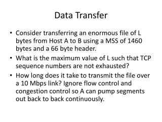
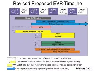
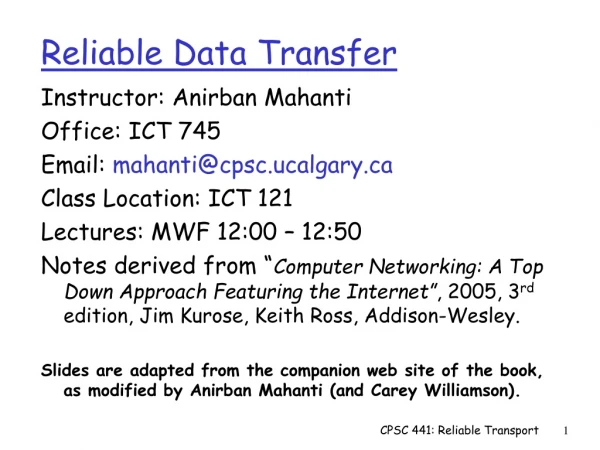
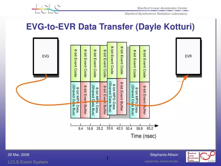
EVG-to-EVR Data Transfer (Dayle Kotturi). EVG Event Time Line – 4 Fiducials. 360Hz Fiducial. F3 (n=3). F1 (n=1). F2 (n=2). F0 (n=0). 2.8. 5.6. Time (msec). 0. 9.3. 8.3. 1.0. R3. HW starts sending event codes, starting with fiducial event code. R2. R1. R0.

E N D
EVG Event Time Line – 4 Fiducials 360Hz Fiducial F3 (n=3) F1 (n=1) F2 (n=2) F0 (n=0) 2.8 5.6 Time (msec) 0 9.3 8.3 1.0 R3 HW starts sending event codes, starting with fiducial event code R2 R1 R0 Receive Fn+3 PNET, determine and send Fn+3 LCLS pattern, advance pipeline (n-2->n-1->n), set event codes in alternate RAM for FN=1 P3 P0 P2 P1 B0 B-3 120Hz BEAM HW finishes sending event codes, switch RAMs R3 R2 R1 R0
P-1 P-1 P-2 P-3 P2 P2 P1 P0 P0 P-1 P-2 P-3 P-1 P-2 P-3 P-4 P3 P2 P1 P0 P0 P0 P-1 P-2 P1 P0 P-1 P-2 P1 P1 P0 P-1 PATTERN n-3 PATTERN n-2 PATTERN n-1 PATTERN n P2 P1 P0 P-1 EVR Event Time Line – 4 Fiducials 360Hz Fiducial F3 (n=3) F1 (n=1) F2 (n=2) F0 (n=0) 2.8 5.6 Time (msec) 0 9.3 8.3 HW starts receiving event codes, starting with fiducial event code R3 R2 R1 R0 Process Pn-3 pattern, advance pipeline (n-3->n-2->n-1->n), and prepare BSA based on the n records L2 L3 L0 L1 Receive Fn+3 LCLS pattern and copy into temporary storage P3 P0 P2 P1 B0 B-3 120Hz BEAM HW finishes receiving event codes R3 R2 R1 R0
Trigger Event Time Line – 1 Beam Pulse (B0) Record processing (event, interrupt) Hardware Triggers Receive pattern for 3 pulses ahead Post-Beam Acq Beam Event Timestamp, pattern records, and BSA ready Kly Standby Acq Trigger Last Event (255) Received Laser Control Fiducial Event (1) Received Fiducial B0 F3 30 500 0 1023 Time (usec) 0.3 Event Codes 1-111, 128-255
BSA Enable Records (2) PULSEID Fiducial sub Record Pattern n (120Hz) Record EVG 360 Hz Data Flow Diagram LNK1 LNK3 Advance Times Pattern (360Hz) Record BSA EDEF History/Snapshot Records first dbProcess LNK2 FLNK INP LCLS Time Stamps Pattern n-1 Record Pn – New Pattern Processing FLNK INP Sequence RAM Setup Records FLNK High Priority PNET Task Pattern n-2 Record INP FLNK FLNK Fanout Record second dbProcess En – Set Event Codes Write to Pipeline Pattern n-3 sub Record Event Event Task post_event BSA EDEF Check, Set, Init Records PNET Avail ISR FLNK FLNK Ln – Send Pattern Module720 Diagnostics Records Data Data Check sub Record INP VME PNET Data Space NTP Client System Time Stamp Bunch Charge Determination Records BSA EDEF Records
BSA Enable Records (2) PULSEID Ln - Fiducial Event Processing Fiducial sub Record Pattern n (120Hz) Record EVR 360 Hz Data Flow Diagram LNK3 LNK1 Advance Times Pattern (360Hz) Record SLC-Aware EVR Check Records Event ISR LNK2 LNK4 Event second dbProcess FLNK INP VME, PCI Pattern n-1 Record LCLS Time Stamps Wakeup INP FLNK FLNK High Priority EVR Task Pattern n-2 Record INP Fanout Record Write to Pipeline Pn - New Pattern Processing first dbProcess FLNK Data Avail ISR EDEF Meas Severity Record Pattern n-3 sub Record Modulo 720 Diagnostics Records Data post_event VME, PCI Pattern Data Space dbProcess Event Task BSA Reset Sequence Records
Pattern Subroutine Record • C – Time slot (1 to 6) • D,E,F,G,H – MODIFIER1 to 5: Beam Modifiers (4 for PNET, 1 for 20 EDEF active bits and 12 TBD bits) • I – BUNCHCHARGE (in picoCoulombs, value normally between 200 to 1000) • J – BEAMCODE decoded from MODIFIER1 by pattern sub record • A, B – EDEF measurement severity masks used to create EDEF measurement severities • K – EDEF average done mask • L - PULSEID decoded from lower 17 bits in the LCLS timestamp by pattern sub record (0x1FFFF = invalid)
EVR Data Contents and Order • EVG: • 4 PNET 32 bit unsigned integers (MODIFIER1 to 4). • EVR: • 2 16 bit unsigned integers – header consisting of waveform type (pattern or TBD) and version number • 4 PNET 32 bit unsigned integers (MODIFIER1 to 4). • 1 LCLS 32 bit unsigned integer (MODIFIER5) • 4 LCLS 32 bit EDEF masks: • Average done • Don’t use minor severity data in average • Don’t use major severity data in average • Initialize – rearm compress records and reset averages • 2 LCLS timestamp 32 bit unsigned integers • 1 bunch charge 32 bit unsigned integer (BUNCHCHARGE)
LCLS Pipeline Timestamps • Table of 4 EPICS timestamps/status, protected by mutex. Each timestamp is 2 32bit integers and each status is 1 32bit integer: • First timestamp integer: #secs since 1990 • Second timestamp integer: #nsecs since last second but with the lower 17bits containing encoded pulse ID • Status integer: 0 = OK, -1 = invalid • Each timestamp/status is associated with an index: • 0 = current pulse (Pn) • 1 = next (upcoming) pulse (Pn-1) • 2 = two pulses in the future (Pn-2) • 3 = three pulses in the future (Pn-3) • The table is initialized with system time and invalid status. The timestamp and status is updated at 360Hz during fiducial and pattern processing
LCLS Event Code Timestamps • Table of 256 EPICS timestamps/status, protected by mutex. Each timestamp is 2 32bit integers and each status is 1 32bit integer: • First timestamp integer: #secs since 1990 • Second timestamp integer: #nsecs since last second but with the lower 17bits containing encoded pulse ID • Status integer: 0 = OK, -1 = invalid • Each timestamp/status is associated with an event code from the EVR. Event code 0 has the current timestamp updated at 120hz (only on the 2 time slots served by the IOC). • The table is initialized with system time and invalid status. The timestamp and status is updated whenever an event code, with an enabled IRQ, is received by the EVR. • All records on the IOC uses a timestamp from this table depending on the record’s TSE field. The default TSE is zero - these records use the event code 0 timestamp. If the status is invalid, the record timestamp will be system time with an encoded invalid pulse ID.
Common EVG and EVR Software Error Conditions • Data/PNET Avail ISR: • Overwrite message space – update counter • No space available (space currently being readout by the task) – update counter • Check sum error (EVR only for now) – update counter • Task is busy (taking too much time) – update counter • Data Processing (record set invalid): • No data available (TIMEOUT) • Other read error or version/type mismatch (INVALID_DATA) • Error creating (EVG) or writing (EVR) LCLS timestamp (INVALID_TIME) • Upstream MPG (EVG) or EVG (EVR) is unsynchronized (MPG_IPLING) • Fiducial Subroutine Record Processing: • Error advancing LCLS timestamps - set error flag. • Pulse ID error (any invalid PULSEID or non-consecutive PULSEIDs) – set appropriate counters. Set error flag. If the upcoming 3 pulses are the same, set timestamp to invalid.
EVG-only Software Error Conditions • PNET Data Check Subroutine Processing: Set record invalid and reset pulse ID and base rate modulo counter if any of these conditions is true: • MPG is IPLing • Time slot not synchronized with MPG • Time slot pattern (SEQCHK) not synchronized with MPG • Time slot and time slot pattern mismatch • Modulo720 not synchronized with MPG • Pulse ID not synchronized with MPG • Pattern Creation Subroutine Processing: • Error getting system time – set record and timestamp to invalid and don’t send pattern to EVRs. • Any of the above errors – set record invalid but send pattern on to EVR with the MPG_IPLING bit set.
EVR Hardware Error Conditions (John Dusatko) • Unplugged fiber: the EVR has a bit in its CSR called RX_VIO. This bit gets set when there is either a bit error or loss of signal. This toggles the CSR bit, lights up the red front panel "RX ERR" LED and also can be programmed to generate an interrupt. • Binary input record is processed every 2 seconds to check this condition. • The EVR also has a "heartbeat" mechanism which looks like it basically does a watchdog function: the EVG can send out a special heartbeat reset event code that resets the EVR's heartbeat counter. The counter seems to have a hard-wired timeout of 1.6 sec. The timeout condition sets a register bit as well as can be programmed to generate an interrupt. So it looks like they thought of some error checking mechanisms. • Software ignores this condition since it detects missing fiducials within 0.06 sec instead and then sets records invalid (TIMEOUT error).
EVG Hardware Error Conditions • No errors when fiducial or clock is missing • PNET SDLC and other errors • Ignored by software – will result in TIMEOUT and unsynchronized data errors. • Loss of PNET (MPG down, cable disconnected, etc) • Software times out in 0.04 sec, sets records invalid, and sends data to EVR with an invalid pulse ID and the MPG_IPLING bit set.